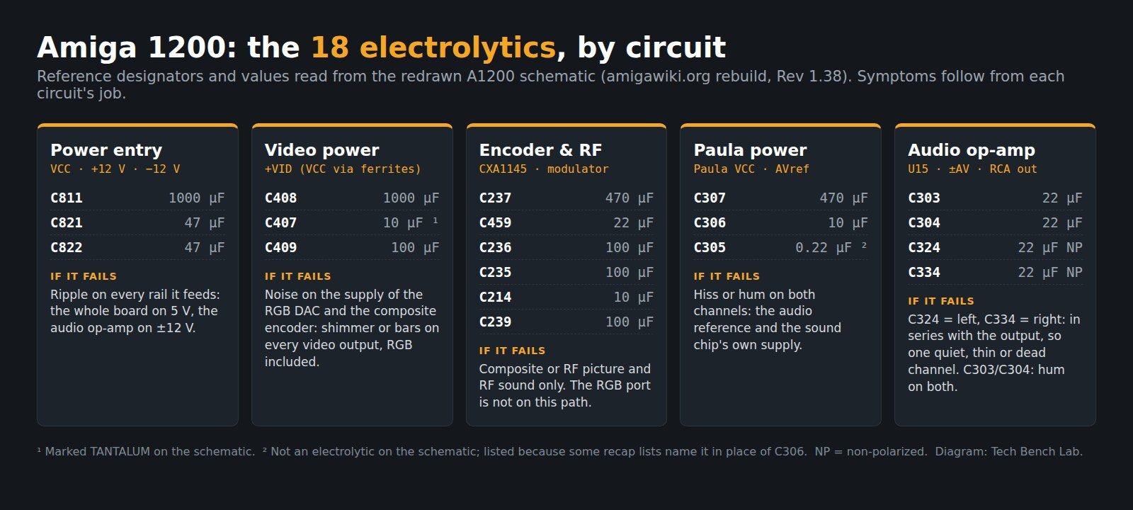
The Amiga 1200 motherboard has 18 electrolytic capacitors: 14 surface-mount cans and 4 through-hole parts. That count comes from the schematic, not from a kit. We checked six recap lists that circulate on kit shops, repair blogs and forums against that schematic, and none of them matches it completely. Two name a part that is not an electrolytic, or one that does not exist. Two add a nineteenth 10 µF. Five of the six treat the two audio output capacitors as ordinary polarized parts, and the schematic marks them non-polarized.
Below is the full list with value, position and circuit, what a failed one does, and where the published lists go wrong. Last checked 18 September 2026. The master source is the redrawn A1200 schematic published by amigawiki.org (sheet revision 1.38), linked at the end.
The 18 positions, from the schematic
Voltage ratings are not printed on the schematic, so the “rail” column gives the DC each part actually sits on. That is the number to size a replacement against. The original ratings quoted in recap lists vary; they are covered under replacements below.
| Ref | Value | Circuit | Sits on | What a failed one does |
|---|---|---|---|---|
| C811 | 1000 µF (through-hole) | Power connector | VCC, 5 V | 5 V bulk filter for the whole board |
| C821 | 47 µF | Power connector | +12 V | Ripple on +12 V, which reaches the audio op-amp |
| C822 | 47 µF | Power connector | −12 V | Ripple on −12 V, same path |
| C408 | 1000 µF (through-hole) | Video power | +VID, 5 V after ferrites | Noise on the RGB DAC (U30) and the composite encoder (U12) |
| C407 | 10 µF, marked tantalum | Video power | +VID | Same rail, high-frequency end |
| C409 | 100 µF | Video power | +VID at the encoder | Noise on the encoder’s supply |
| C237 | 470 µF (through-hole) | Video encoder | Composite out → CN10 | Dim, smeared or missing composite picture |
| C459 | 22 µF | Video encoder | CXA1145 Vref (pin 14) | Unstable composite and RF picture |
| C236 | 100 µF | Video encoder | Composite sync out → RF modulator | RF picture only |
| C235 | 100 µF | Video encoder | Encoder audio out → RF modulator | RF sound only |
| C214 | 10 µF | Video encoder | Encoder audio in | RF sound only |
| C239 | 100 µF | RF modulator | Modulator +5 V | RF output only |
| C307 | 470 µF (through-hole) | Audio power | Paula VCC, via a 1 Ω resistor | Noise on the sound chip’s own supply |
| C306 | 10 µF | Audio power | AVref, the audio mid-rail reference | Hiss or hum on both channels |
| C303 | 22 µF | Audio decoupling | +AV (+12 V via 10 Ω) | Hum or distortion, both channels |
| C304 | 22 µF | Audio decoupling | −AV (−12 V via 10 Ω) | Hum or distortion, both channels |
| C324 | 22 µF non-polarized | Audio out | Op-amp pin 1 → left RCA | Quiet, thin or dead left channel |
| C334 | 22 µF non-polarized | Audio out | Op-amp pin 7 → right RCA | Quiet, thin or dead right channel |
By value that is three 10 µF, five 22 µF, two 47 µF, four 100 µF, two 470 µF and two 1000 µF. The iKod.se count per value matches this exactly. The symptom column is what each circuit’s job implies. It is not a measurement, and leaked electrolyte can take out a trace next to a capacitor that has nothing to do with the symptom you are chasing.
Where the published lists disagree with the schematic
These are the lists that come up first when you search for an A1200 cap list. Most are careful work, and most of the errors are a single character. On a board where a wrong reference means desoldering the wrong part, one character is enough.
| List | Positions | Where it differs from the schematic |
|---|---|---|
| Retro Rewind kit list | 18 named | Lists C305 as 10 µF and leaves out C306. On the schematic C305 is 0.22 µF, a small cap in parallel with C306. |
| Acill parts list, amiga.org (2016, rev 1D1) | 18 named | Lists C238 and leaves out C236. There is no C238: R238 is a resistor in the RF audio path. |
| Retro Fixer (rev 1D4) | 18 named | “C2408“, a typo for C408 |
| Retro Commodore Q&A (rev 1D4) | 18, counts only | No reference designators, so there is nothing to check a position against |
| AmiBay thread, 2013 (two lists) | 19, counts only | Both have four 10 µF parts. The fourth is almost certainly the C305 confusion. |
| iKod.se (per value) | 18, counts only | Counts match. Uprated voltages are listed as replacements, not as the originals. |
The C305 mix-up is old. In an April 2016 amiga.org thread, a member who was socketing Paula found C305 listed as both 0.22 µF and 10 µF. The schematic settles it: “Edit: But the schematics list this as 0.22uF, audio power (not decoupling).” If your board has an electrolytic in a position your list does not match, trust the schematic and the part that is physically there. Don’t trust the kit.
The part nobody covers: two of these capacitors set a frequency, not just a filter
Most of the 18 are supply filters. If one loses half its capacitance, the rail gets noisier and you might never notice. Two are different, because they sit in series with a signal. Together with the resistance after them they form a high-pass filter, f = 1/(2πRC). When the capacitance falls, that corner frequency climbs into the signal.
C237, composite video. It drives the RCA jack through a 75 Ω resistor into the TV’s 75 Ω input, so it sees about 150 Ω. An EDN design article on video coupling capacitors by Fairchild’s Duane Sorlie uses the same load: 220 µF gives a 4.8 Hz corner, “adequate to pass the frame rate”, and “most applications have more stringent field tilt requirements and use a 470 or 1,000-µF device”. Commodore chose 470 µF.
| C237 capacitance | Corner at 150 Ω | Against a 50/60 Hz field |
|---|---|---|
| 470 µF (as designed) | 2.3 Hz | Far below the field rate |
| 220 µF | 4.8 Hz | EDN’s “adequate” floor |
| 100 µF | 10.6 Hz | Margin shrinking |
| 47 µF | 22.6 Hz | Within a factor of 3 of the field rate: expect brightness tilt |
C324 and C334, audio. After each one on the board there is a 1 kΩ series resistor, then a 360 Ω resistor to ground at the jack. With a typical 10 kΩ line input on the other end, each capacitor sees about 1.35 kΩ. At 22 µF the corner is 5.4 Hz. Let the capacitor dry out to 2.2 µF and it moves to 54 Hz; at 1 µF it is at 118 Hz. That is the “thin” sound people blame on the Amiga’s filter. It is one channel at a time, which is how you tell it from a Paula or op-amp fault. In a January 2017 Lemon Amiga thread about a machine that came back from a recap with no sound, these two were the first parts other members pointed to: “C324 and C334 are directly in line with the audio output”.
The same arithmetic explains the non-polarized marking. The op-amp runs from ±12 V, so its output sits near 0 V, and the jack is at 0 V too. There is no DC to polarize the capacitor, so the schematic calls for a bipolar part. A polarized 22 µF with its + side toward the op-amp is what most kits supply, and it will work. A bipolar 22 µF is the part the design calls for.
Choosing replacements
- Size voltage against the rail in the table, not against a list. The lists disagree about the originals: the four 100 µF parts appear as 6.3 V in Retro Rewind and Retro Commodore and as 16 V in Retro Fixer and Acill. Two of them (C409, C239) sit on 5 V. A 6.3 V part there has 1.3 V of margin. A 16 V or 25 V part of the same diameter is the better buy, if it fits the pad.
- ±12 V positions (C821, C822, C303, C304) need at least 16 V, and 25 V is kinder. Every list that names these positions rates them at 16 V or higher.
- Leave C407 alone unless it is actually bad. The schematic marks it tantalum. It is not in the same failure family as the aluminium cans around it.
- Tantalum is not an upgrade on the ±12 V rails. Some sellers offer tantalum for the 47 µF pair. A 16 V tantalum on a 12 V rail runs at 75% of its rating. Solid tantalum is usually derated much further than that, and when it fails it tends to fail short. Aluminium or polymer is the safer choice here.
- Size. The amiga.org parts list gives 5 mm cans for the 10 µF parts, 6.3 mm for the 22, 47 and 100 µF parts, 8 mm radials for the 470 µF pair and 10 mm radials for the 1000 µF pair.
Limits and common mistakes
- One schematic, several board revisions. The designators above match the lists written for rev 1D1 and 1D4 boards. Before you desolder anything, compare every silkscreen reference on your board with the table.
- Twisting the old cans off lifts pads. The A1200’s SMD pads are small, and traces under a leaked cap are already weakened. Hot air or two irons, then clean the electrolyte residue before fitting the new part. Our hot air guide covers temperatures.
- Replacing a leaked cap does not repair the corrosion. Check continuity from each new pad to where its trace goes on the schematic. The multimeter guide covers the settings that matter.
- The power supply is a separate job. The external A600/A1200 brick (391029-03) has ten capacitors of its own, including a 47 µF 385 V mains part. Jani’s list covers it, and it carries a mains shock warning for good reason.
Sources
- A1200 schematic, rebuilt for amigawiki.org, sheet revision 1.38 (06.09.2012), 16 sheets
- EDN / Duane Sorlie (Fairchild), “AC coupling capacitors in video designs”, 2007
- amiga.org: “A1200 audio decoupling capacitor” (Acill’s 1D1 parts list; C305 = 0.22 µF)
- Lemon Amiga: no sound after a recap, C324/C334
- Retro Rewind: Amiga 1200 cap list
- Retro Fixer: Amiga 1200 recap (rev 1D4)
- Retro Commodore Q&A: capacitors for A1200 1D4
- AmiBay: Amiga 1200 capacitor list (2013)
- iKod.se: Amiga capacitor lists
- World of Jani: Amiga 500/600/1200 power supply capacitor list
FAQ
How many capacitors do I need to recap an Amiga 1200?
Eighteen electrolytics on the motherboard: 3 × 10 µF, 5 × 22 µF, 2 × 47 µF, 4 × 100 µF, 2 × 470 µF and 2 × 1000 µF. The last four are through-hole. A kit with a fourth 10 µF is counting C305, which the schematic shows as 0.22 µF.
My A1200 has sound on one channel only. Which capacitor?
C324 for left, C334 for right. They are the only electrolytics in series with a single channel. Anything that affects both channels at once (C303, C304, C306, C307) is further upstream.
RGB is fine but composite is dark or smeared. Is that the caps?
Start with C237, the 470 µF through-hole part that couples the composite output. The RGB port does not pass through it, which is why RGB can look perfect while composite fails. C459 and the +VID filters (C408, C409) come next.