A hot air rework station turns “I can’t touch that” into a procedure: pulling a BIOS chip to read it on a programmer, swapping a shorted capacitor, replacing a torn-off USB connector. It is also the tool that destroys more boards than any other on a beginner’s bench, because nothing warns you that you’ve gone too far until a pad lifts. This guide covers picking your first station, the temperatures and airflow that actually work, the technique that preserves the board, and the industry limits almost nobody mentions in a beginner tutorial.
What Hot Air Actually Does (and What It Doesn’t)
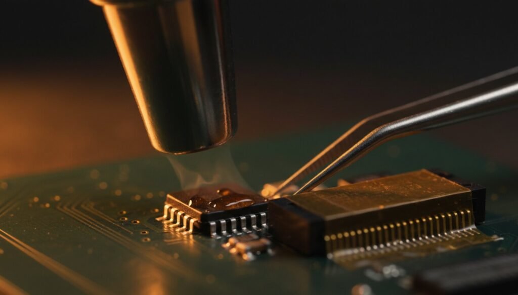
A soldering iron heats one joint by contact. Hot air heats a region by convection — every joint under the nozzle at once. That is the whole point: an 8-pin SOIC has eight joints that must all be liquid at the same instant before the chip comes free, and no amount of skill with an iron gets you there.
What it does not do is replace the iron. Through-hole parts, wires and single-pad touch-ups are all faster with a tip. The two tools split the bench: air for multi-terminal SMD, iron for everything else. If you can only buy one, buy the iron. If you already have a decent iron, hot air is the biggest single capability jump available to you.
Choosing Your First Station
The market splits into three tiers, and only two are worth your money as a beginner.
- Air-only, 858D-style. The classic entry point. Cheap, widely cloned, genuinely adequate for SMD passives, SOIC/TSOP chips and connectors. The weakness of the cheapest units is a diffuse air stream and a readout that drifts.
- 2-in-1 (air + iron in one base). The best value for someone building a bench from scratch — one supply, one footprint, controlled temperature on both sides. This is where most repair techs start.
- Hot air + preheater + IR, “professional BGA” systems. A different price class and skill class. Skip it until you know you need it.
What matters on the spec sheet, in order: stable closed-loop temperature control (a unit that overshoots by 40 °C every cycle will cook something eventually), independently adjustable airflow, a heater around 700 W so the stream doesn’t collapse when you open the flow, and a nozzle set included. You’ll use the medium 8–10 mm round nozzle roughly 90 % of the time.
Ignore any entry-level station advertising “professional BGA rework.” A bare air pencil cannot bring a whole board up to temperature evenly, and heating a large BGA from the top alone is how boards warp.
Temperatures and Airflow: Starting Points, Not Gospel
The numbers below are bench starting points. Adjust from there by watching the solder, never by copying someone else’s display reading.
| Job | Temperature | Airflow | Nozzle |
|---|---|---|---|
| Small SMD (0402–1206, SOT-23) | 300–330 °C | Low | Small (4–5 mm) |
| SOIC / TSOP / SOP (BIOS, NAND) | 330–360 °C | Medium | Medium (8 mm) |
| Connectors, parts with plastic | 320–350 °C | Medium-low | Medium, shielded |
| Large ground-plane-connected parts | 360–380 °C | Medium-high | Medium-large |
| Shrink tubing, heat-set work | 150–200 °C | Low | Any |
Leaded versus lead-free is a real ~35 °C difference, not folklore. Eutectic Sn63/Pb37 melts at 183 °C. SAC305 — the lead-free alloy in nearly everything built after 2006 — has a solidus of 217 °C and a liquidus of 220 °C per the alloy datasheets. So a lead-free joint needs meaningfully more heat in the board before it flows. If solder isn’t moving, raise in steps of 10–15 °C and give it more time. Never jump 50 °C.
The Display Is Not the Joint Temperature
This is the single most useful thing to internalise. The thermocouple sits in or near the heating element — not at your solder joint. Between the two there is a nozzle, a few centimetres of open air, and a board actively conducting your heat away into its copper planes.
The consequences are practical. Air temperature falls sharply with distance, so 1 cm versus 3 cm is a different job at the same display setting. A four-layer board with big ground planes swallows heat that a two-layer board would have handed straight to the joint. Two stations set to “350” will not deliver the same result — and neither will your own station on a different board.
So calibrate to reality, not to the number: flux it and watch. Solder that goes shiny and pulls into a meniscus is liquid. That visual cue is your real thermometer.
The Removal Technique That Preserves the Board
- Flux first, always. Gel flux on every terminal before the air comes on. It improves heat transfer into the joints, keeps oxides from forming at temperature, and makes the solder release evenly instead of one corner at a time.
- Protect the neighbours. Polyimide tape over adjacent plastic connectors, displays and anything near a battery. DuPont’s own data sheet cites successful use of the film up to 400 °C — which is exactly why it’s the standard bench masking tape.
- Preheat the region. 30–60 seconds of circular motion from 2–3 cm away, letting the whole area rise together. Skipping this is how you crack joints and lift traces: thermal shock, not peak temperature, does that damage.
- Close in and keep moving. Nozzle at roughly 1 cm, constant circular motion around the part. Parking the stream on one spot lifts pads and scorches solder mask.
- Test with tweezers, never force. Touch the component lightly. When every joint is liquid it floats — you’ll feel it swim. If it resists, it is not ready: more flux, a few more seconds, or 10 °C more. Prying a part off a solid joint takes the pad with it.
- Lift straight up and park it somewhere heat-safe. Not on your cutting mat.
Putting It Back
Wick the pads clean with braid and flux, tin them very lightly, position the part, then bring the air back. When the solder goes liquid, surface tension pulls the component into alignment on its own — the one moment in this hobby where physics does the precision work for you. A USB microscope earns its price here more than anywhere else on the bench.
The Part Nobody Covers: The Industry Has Hard Numbers
Beginner tutorials talk about hot air as if the only risk were “too hot.” The electronics industry has published limits for exactly this, and they are stricter than most hobbyists assume. From IPC/JEDEC J-STD-020, the standard that governs how surface-mount parts are qualified for reflow (figures as tabulated in Texas Instruments’ application report SPRABY1A):
- Peak package body temperature (Tc) is capped at 260 °C for thin packages under 1.6 mm, dropping to 250 °C and 245 °C as packages get thicker and bulkier. That is the temperature of the part, not of your air. It is why “just turn it to 450” is not a strategy.
- Ramp rate above liquidus must not exceed 3 °C per second. Blasting a cold part with 400 °C air at full flow violates this easily.
- Total time from room temperature to peak should not exceed 8 minutes. The beginner who has been waving a nozzle over a stubborn chip for five minutes is not being careful — they are cooking the package.
And the failure mode that catches salvaged parts: popcorning. Plastic IC packages absorb atmospheric moisture. Heat it fast enough and that water flashes to steam inside the package, delaminating or cracking it — sometimes with an audible pop, often with no visible sign at all until the chip misbehaves later. This is what the Moisture Sensitivity Level (MSL) rating on a datasheet is about. Per J-STD-033 floor-life figures, an MSL 3 part has 168 hours of exposure at 30 °C/60 % RH before it’s supposed to be baked; MSL 4 has 72 hours, MSL 5a just 24.
The bench takeaway: that BIOS chip you pulled two years ago and left in a drawer is moisture-loaded. If you’re reinstalling a salvaged chip that matters, a low-temperature bake first (well below soldering temperature — the standard’s drying references top out around 125 °C for bare parts) is not paranoia. And either way, the preheat step above does double duty: it drives moisture out gently instead of explosively.
Five Mistakes That Kill Boards
- Airflow at maximum. The famous SMD blizzard: your 0402s leave the board and are never seen again. Airflow is a control, not a switch.
- Impatience. Pulling a part before every joint is liquid. It takes the pad with it, every time.
- No masking. Plastic connectors, ribbon sockets and nearby lithium cells all melt or vent long before solder does.
- Board loose on the bench. Use a holder. A board that shifts when your tweezers touch it will shift at the worst moment.
- Practising on a customer’s board. Scrap boards are free and endless. Ten removals and ten reinstalls on a dead motherboard teach more than any video.
What About BGA?
Reballing a chipset, GPU or eMMC is genuinely different work: it needs bottom-side preheat (the whole board to roughly 150 °C before the top-side attack), stencils, solder spheres and a lot of practice. With a bare air pencil and no preheat, the odds of warping the board are high. Learn passives, then SOIC, then TSOP; practise BGA on scrap; buy the full setup only when the work justifies it. We covered the honest version of that decision in when BGA reballing actually fixes the board.
Buying rather than using? The spec sheets are less comparable than they look: we put the official airflow figures for 12 hot air stations side by side and found six different units for the same column — including one headline number that is not litres per minute at all.
Where This Sits in a Repair
Hot air is rarely the first tool you reach for — it executes the decision the diagnosis already made. A typical path: current draw on a bench power supply narrows the fault to a rail; that usually lands on a shorted MOSFET or a dried-out filter capacitor; hot air removes and replaces it. On the firmware side it’s more direct still — hot air lifts the 25xx SPI flash, a CH341A or RT809H reads and writes it, hot air puts it back. An SOIC-8 clip on an XGpro-driven programmer often works in circuit and saves you the trip — but when it doesn’t, the station is what gets you unstuck.
FAQ
Does hot air replace a soldering iron? No. They’re complementary: air for multi-terminal SMD and anything with a thermal pad, iron for through-hole, wires, and touch-ups. Nearly every job uses both.
What flux should I use? A reputable no-clean or rosin gel flux in a syringe. Avoid plumbing paste — it’s acidic and will corrode the board over months.
Is polyimide tape really necessary? It costs almost nothing and saves connectors. With desoldering braid, isopropyl alcohol and fine tweezers, it’s the core consumable kit.
Why did my solder mask turn brown? Too hot, too close, or parked in one spot too long. Discolouration is a warning shot — the next step past it is delamination.
Can I use hot air to remove a BIOS chip and program it externally? That’s the classic workflow. Air off the 25xx, read/write it on a CH341A, RT809F or T48, air it back on.
Display says 350 °C but nothing melts. Is the station broken? Probably not. Check nozzle distance, then airflow, then whether the joint ties into a large ground plane. Big copper areas sink heat faster than a small nozzle delivers it — that calls for a bigger nozzle and more flow, not a higher number.
Verdict
Hot air rework is 20 % equipment and 80 % technique. A modest 2-in-1 station with stable control and a decent nozzle set handles everything short of BGA, for years. What separates the tech who removes a chip in ninety seconds from the one who lifts three pads is not the station — it’s flux, preheat, constant motion, and the discipline to wait for the part to float instead of pulling it. Buy an honest station, spend an afternoon destroying a scrap board on purpose, and you unlock a category of repair a soldering iron alone will never reach.