A multimeter gives you a number. An oscilloscope gives you the movie. That is the difference between knowing a rail sits at 5 V and seeing that those 5 V are riding on 400 mV of sawtooth, collapsing in a ramp, or switching off fifty times a second. This guide covers what a scope actually shows on a repair bench, whether you need one yet, which three specs are worth arguing about — and the accessory that quietly decides whether your measurement is true: the probe.
What the Scope Shows That Your Meter Can’t
A scope draws voltage against time: horizontal is time, vertical is volts. That matters because almost nothing on a modern board is a still voltage.
- Supply ripple. The meter says “5.02 V”. The scope shows the 400 mV sawtooth sitting on top of it that keeps resetting the machine — usually a dried-out capacitor.
- Clocks and crystals. Without a clock the processor is a rock. Only a scope confirms that the 25 MHz crystal is really oscillating.
- Digital lines. UART, I2C and SPI traffic appears on screen — you can see whether one chip asks and the other answers.
- PWM. Backlight drivers, fan control and switching supplies work by varying pulse width. Invisible to a meter, obvious on a scope.
Do You Actually Need One Yet?
Honest answer: not on day one. A decent multimeter, a bench power supply and a method will close most of your tickets, because most faults are power faults. The scope earns its space later, when every rail measures correct and the board still refuses to wake up (clock? reset? enable?), or when the fault is intermittent and everyone blames “a bad solder joint”.
Put differently: buy the scope when the answer you need is a shape, not a value.
The Three Specs Worth Arguing About
Bandwidth is the frequency at which the scope’s own response has already fallen 3 dB — the point where amplitudes are, in Tektronix’s phrasing, “overly attenuated and measurement results may be unpredictable”. Tektronix publishes the sizing rule in its XYZs of Oscilloscopes primer as the 5 Times Rule: oscilloscope bandwidth ≥ highest frequency component of the signal × 5, which “will give you less than ±2% error in your measurements”.
Read that carefully, because it is where buying guides get lazy. A 25 MHz crystal is not a 25 MHz sine wave on the board — it is an edge, and edges carry content far above their repetition rate. By the 5 Times Rule, characterising it faithfully wants ~125 MHz of scope. But on a repair bench you rarely need the amplitude to be faithful — you need to know whether it oscillates at all. A 100 MHz scope answers that on every crystal you will meet, and a 50 MHz scope will still show you something. That is the honest version of “100 MHz is the sweet spot”.
The same primer relates bandwidth and rise time with Bandwidth = K / Rise Time, where K is 0.35 for scopes below 1 GHz. So a 100 MHz scope cannot show an edge faster than about 3.5 ns, no matter how the screen looks. Tektronix’s own table of what logic families produce is the reality check:
| Logic family | Typical signal rise time | Calculated signal bandwidth |
|---|---|---|
| TTL | 2 ns | 175 MHz |
| CMOS | 1.5 ns | 230 MHz |
| GTL | 1 ns | 350 MHz |
| LVDS | 400 ps | 875 MHz |
Your 100 MHz scope rounds off every one of those edges. It still tells you the line toggles, which is the question you were asking.
Sample rate is the second number. Real-time sampling, per the primer, “is ideal for signals whose frequency range is less than half the oscilloscope’s maximum sample rate” — the Nyquist floor, not a target. The real target is in the same document: sin(x)/x interpolation, which is how the scope draws curves between samples, “is the preferred method for applications where the sample rate is 3 to 5 times the system bandwidth”. For a 100 MHz instrument that means 300–500 MSa/s minimum, so the 1 GSa/s entry bench scopes advertise is genuinely enough. Watch the footnote instead: on most models that headline rate is what you get with one channel running, and it halves when you switch on the second.
Channels. Two, minimum. Half the value of the instrument is comparing two things at once — input against output, clock against data, enable against rail. Four channels are a development and automotive luxury; repair rarely misses them.
The Part Nobody Covers: Your 10 MΩ Probe Is 600 Ω at the Crystal
Every passive probe is sold on its resistance. That resistance is a DC number, and DC is not what you bought the scope for.
Tektronix’s ABCs of Probes states the mechanism plainly: capacitance at the probe tip has a reactance of Xc = 1/jωC, so “as frequency increases, the capacitive reactance decreases. The result is increased loading at high frequencies.” The primer publishes the tip capacitance of its own probes — 8 pF for the 10X P6139B, 12 pF for the 10X TPP1000, and 100 pF for the 1X P6101B.
Run those through the formula. Using a round 10 pF for a typical 10X probe and the published 100 pF for a 1X:
| Signal on the board | 10X probe (≈10 pF) | 1X probe (100 pF) |
|---|---|---|
| 100 kHz I2C bus | ≈159 kΩ | ≈16 kΩ |
| 1 MHz PWM edge content | ≈16 kΩ | ≈1.6 kΩ |
| 8 MHz SPI clock | ≈2 kΩ | ≈200 Ω |
| 25 MHz crystal | ≈640 Ω | ≈64 Ω |
That 10 MΩ probe is a 640 Ω load by the time you touch the crystal. A crystal oscillator circuit is a deliberately weak, high-impedance loop; hang 640 Ω across it and a marginal one simply stops — which is why the classic beginner experience is “the board died when I probed the clock, so I must have shorted something”. You did not short anything. You loaded it.
Two rules fall straight out of the table. First: leave the probe in 10X and tell the scope’s channel menu that it is in 10X. A 1X probe on a 25 MHz node is a 64 Ω load — it is not a measurement, it is a fault you installed. Use 1X only for slow, low-amplitude signals on stiff nodes. Second: when a clock looks dead, probe the driven side of the oscillator or a downstream buffer, not the crystal can itself. If a marginal oscillator survives the probe, it is marginal — that is a finding, not an accident.
Compensate the Probe, Then Shorten the Ground Lead
Clip the probe onto the calibration terminal on the front panel, look at the square wave, and turn the small screw on the probe body until the corners are square and flat — not rounded, not peaked. Thirty seconds, and it is the difference between an amplitude you can trust and one you cannot. Do it every time you swap the probe to another channel.
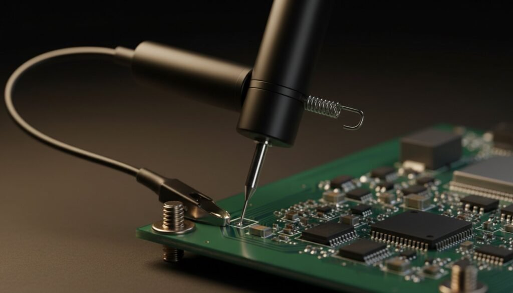
Then leave the stock ground lead alone. The ABCs of Probes is direct about why: the ground lead is a wire, it has distributed inductance, and “this inductance interacts with the probe capacitance to cause ringing at a certain frequency”. The fix is not clever grounding, it is short grounding — “always use the shortest ground lead provided with the probe. Substituting other means of grounding can cause ringing to appear on measured pulses.” Every bench technician who has chased a phantom overshoot on a clean 3.3 V rail was looking at their own 30 cm of ground wire.
The Ground Clip Is Earth Ground
This is the rule that saves boards and people. The alligator clip on a bench scope probe is bonded, through the BNC shell and the chassis, to the earth pin of your wall outlet. Tektronix puts it in the safety section of the probe primer as an instruction, not a suggestion: “Connect probe ground leads to earth ground only.”
Clip it to anything that is not ground and you have wired that node to earth through the mains cable. On a board fed by your bench supply, you kill a rail. On the primary side of a switching supply, or an old chassis-referenced TV, you create a direct mains short at the tip — with the corresponding fireworks. The beginner’s boundary is simple: probe only isolated circuits — the secondary side, boards fed from your bench supply. Primary-side work needs an isolation transformer or a differential probe, and that is a different chapter.
Three Measurements to Learn On
- Supply ripple. Channel to AC coupling, probe in 10X, ground clip on a real ground near the point. If the scope has a bandwidth-limit button (commonly 20 MHz), switch it on — otherwise you are measuring broadband noise, not ripple. A healthy 5 V rail shows a few tens of millivolts. Hundreds of millivolts point at a dried-out capacitor.
- Crystal. Touch a downstream point in the clock path and look for a sine at the frequency printed on the can. Present means the oscillator lives; absent means clock, load or the chip itself.
- Backlight PWM. On the LED driver output, the square wave changes width as you change brightness. It is the cleanest demonstration there is of average voltage versus waveform.
Where This Sits in a Repair
The scope is the last instrument on the bench, not the first. Narrow the fault with the bench supply’s current reading, confirm parts in circuit with the meter, condemn the MOSFET if that is what it is, and reach for the scope when every rail is correct and the board still will not run. If the answer turns out to be a corrupt firmware image rather than a signal, the job moves to a flash programmer. And if you cannot see the pad you are trying to probe, that is a microscope problem, not a scope problem. And once the instrument is actually on the bench, the follow-up is what to probe and how to read the screen — including the acquisition setting that decides whether you catch the fault at all.
FAQ
Is a USB oscilloscope good enough? The good ones cost about what an entry bench scope costs; the very cheap ones disappoint on bandwidth and on the software. For a first instrument, a bench unit is the safer buy — knobs beat menus when you are troubleshooting.
Do I need 4 channels? Rarely for repair. Two channels cover the daily work. Spend the difference on bandwidth or on a second decent probe.
What about the little DIY kit scopes? The DSO138-class kits are teaching toys. Their bandwidth is measured in hundreds of kilohertz — useful for learning what a waveform is, useless for finding a clock.
Oscilloscope or logic analyser? The scope shows the analogue shape — noise, edge quality, amplitude. The logic analyser decodes long digital conversations. Many modern scopes decode I2C, SPI and UART themselves; look for “serial decode” on the spec sheet, and check whether it is included or a paid option.
My waveform has ringing that shouldn’t be there. Is the board bad? Check your ground lead first, then your probe compensation, then the board. In that order, every time.
Verdict
An oscilloscope does not replace the multimeter — it starts where the multimeter stops. A two-channel 100 MHz bench scope from an honest brand is a decade of bench life, and it unlocks the class of faults that separates the technician who swaps parts from the one who understands the circuit. Just remember what you actually bought: the instrument is only as good as the 10 cm of probe and ground wire at the end of it, and that is the part the spec sheet never argues about.
Sources: Tektronix, XYZs of Oscilloscopes primer, and Tektronix, ABCs of Probes primer. Verified August 2026.