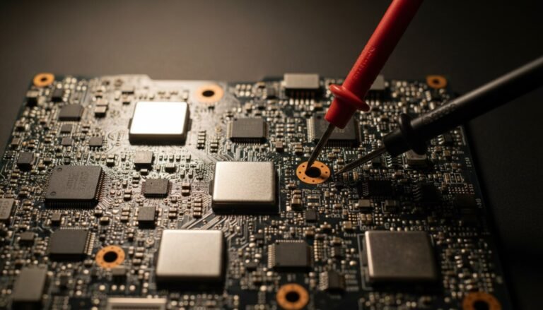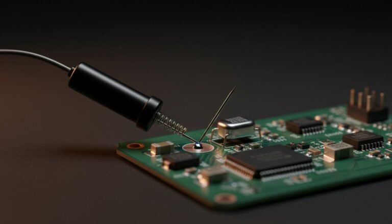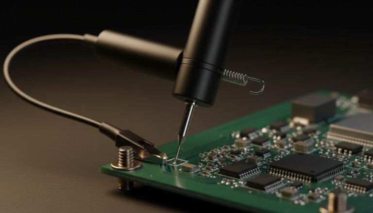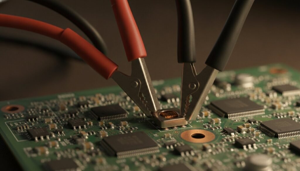
A bench power supply gets sold as a box that makes volts. On a repair bench it is something better: the only instrument that tells you what a dead board is doing before you put a probe on it, and the only one that can push power into a fault without burning the board down while you watch.
Three techniques turn a plain 30 V / 5 A supply into a diagnostic instrument: reading a board by its current draw, standing in for a battery, and injecting voltage so a shorted component heats itself up and tells you where it lives.
The Current Limit Is the Whole Trick (CV vs CC)
Every usable bench supply has two operating modes and switches between them on its own:
- CV — constant voltage: the supply holds the voltage you set and delivers whatever current the load asks for, up to the ceiling you set.
- CC — constant current: the moment the load tries to draw more than that ceiling, the supply drops the voltage — as far down as it has to — to hold the current at the ceiling.
That second mode is the entire reason a bench supply belongs in repair work. A dead short that would pull 15 A from a laptop charger and vaporise a trace becomes a controlled 0.5 A that you chose the size of. The fault stays exactly as big as it was when the board arrived, which is the difference between diagnosing a board and finishing it off.
Set the Limit Before You Connect Anything
Order matters, and most people do it backwards — board first, then go looking for the current knob.
- Leads off the board. Clip red to black and short the output together — on purpose. Every bench supply is designed to sit there shorted all day.
- Bring the voltage up slightly so the supply is actually pushing, then set the current knob. With the output shorted, the supply is in CC and the current display is your ceiling, read directly.
- Separate the leads. Now set the voltage you want.
- Output off. Connect to the board. Then enable the output.
Many supplies have a preview or “set” button that shows the setpoints without enabling the output — use it and skip step 1. What you must never do is guess the ceiling from the knob position and find out you were wrong with the board attached.
Technique 1 — Read the Board by Its Current Draw
Feed the board at its charger connector at the correct voltage and watch the ammeter. Before you probe anything, the number is already telling you a story:
| What the ammeter does | What it means |
| 0.000 A, dead flat | Nothing is energising at all — input fuse, input FETs, or the first regulator never starts. Nothing downstream is worth measuring yet. |
| ~3–30 mA, steady | Standby rails are alive and the board is waiting for the power button. Good news: the fault is further in. |
| Steps up when you press power (0.3 → 0.8 → 1.5 A) | Rails coming up in sequence. If it stalls on a step, the fault lives in that step — you have just narrowed the board to a stage. |
| Jumps straight to your ceiling, voltage collapses (CC) | Short on a main rail. Stop and go to technique 3. |
| Rises and collapses in a loop | Protection tripping: something comes up, fails, and drops everything. Classic partial short or a regulator that can’t hold its rail. |
| Much higher than a healthy board, but never trips | Leakage — a part conducting where it shouldn’t, not yet a hard short. Often the hardest kind to find, and the one the ammeter is best at catching. |
If you work the same models repeatedly, write down what a known-good board pulls at idle and at each step. That one page of notes outperforms most test gear.
Technique 2 — Be the Battery
Phone or laptop board with a “suspect battery”? Remove the battery from the equation entirely: feed the battery terminals directly, at the pack’s nominal voltage, with a low ceiling. Confirm the cell count first — a single cell is 3.7 V nominal / 4.2 V full, 2S roughly 7.4–8.4 V, 3S 11.1–12.6 V. Start around 1 A and raise it only if the board clearly needs more to boot.
If the board lives on the supply and dies on the battery, the pack — or its protection board or fuel gauge — is the fault, found in under a minute without unsoldering anything. It works in reverse too: it takes the charging circuit out of the picture when you suspect the charge path rather than the board.
Technique 3 — Voltage Injection: Make the Short Show Itself
This is the signature technique of board-level repair, and it is simple mechanically and unforgiving if you skip a step.
- Identify the shorted rail — continuity beep between the rail and ground.
- Look up that rail’s nominal voltage in the schematic or boardview. This is the step that separates a repair from a write-off: a 1.05 V rail gets 1 V. Not 5. Definitely not 19.
- Set a low current ceiling — around 0.5 A on a small rail, 1–2 A on a main one.
- Connect: black to solid ground, red to any point on the rail. The metal body of an inductor is the easiest and most forgiving contact point on the whole board.
- Enable the output. The supply will drop straight into CC and hold a fraction of a volt. That is expected — the short is the load.
- Find the heat. Back of a finger over the area; a drop of isopropyl alcohol, watching which spot flashes it off first; or a thermal camera if you own one. Raise the current in small steps only if nothing warms up.
Then read the result. A hot ceramic capacitor is a replacement, full stop. A hot MOSFET needs an actual test before you condemn it. A warm region with no obviously hot component usually means the short is inside an IC — and if that IC is a BGA, you are now in a different conversation about whether reballing is worth it.
One reading fools people: if the whole rail warms evenly instead of one spot getting hot, you are heating copper, not a component. Back the current off — either the short is in a plane or via, or you have been pushing current long enough for the heat to spread, which erases the exact signal you were hunting.
The Part Nobody Covers: Your Output Capacitor Ignores the Current Limit
The CC loop protects you from a load that draws too much. It does nothing at all about the energy already sitting in your supply’s own output capacitor.
If the output is enabled at 5 V and you touch the leads onto a 1.0 V rail, that capacitor dumps into the rail as fast as the wiring allows. The regulation loop responds in microseconds; a capacitor discharging through a few centimetres of copper does not wait that long. The current limit was never in the path.
So the habit, every time, on any low-voltage rail: set the voltage, switch the output off, connect the leads, then enable the output. Same reason you never turn the voltage knob while connected to a live low-voltage rail. On cheap supplies without a real output relay, “off” can still leave charge on the terminals — brush the leads together for a second before moving them to the next point.
Bisection has a shortcut when the board provides one: on the MacBook Air M2 logic board, lifting a single bus fuse separates the input side from everything downstream — see the M2 power sequence and its rails.
Mistakes That Cost Boards
- Wrong injection voltage. The fatal one. Confirm the rail’s nominal value on the schematic or boardview before the leads touch anything.
- Reversed polarity. The current limit guards against excessive current; it does nothing about reverse voltage across a rail. Mark your leads and check them every time.
- Current limit at maximum “to be safe”. Identical to having no limit. Start low and raise deliberately.
- Charger voltage on a battery terminal. The charging circuit belongs in that path. 19 V where 4 V lives does not end well.
- Leaving injection current flowing for minutes. You are depositing watts into a fault; the hot spot you were hunting disappears into the surrounding warmth.
One caveat about the numbers on that display: the supply’s meter and your handheld have their own error budgets and their own loading effects, and neither is a laboratory reference. Reading a multimeter spec sheet properly tells you when to trust the reading and when the instrument is changing the circuit it is measuring.
Where This Sits in a Repair
Once the supply has narrowed the fault to one rail, the next move is component level: testing the resistors, diodes and transistors sitting on it, with the meter instead of the amps display.
The supply narrows the problem to a rail and often to a single component. What you do next is a different set of tools:
- Short on a rail, one part running hot → test the MOSFET properly before you desolder it.
- Slightly high draw, unstable rails, no hard short → filtering, not switching: check the capacitors, including ESR.
- Warm area, nothing obviously hot, the chip sits under a BGA → the reballing decision.
- Zero volts out of a battery pack while the current draw reads nothing at all → the supply is not the instrument for that one. A latched BMS releases on its own published conditions: the six protections and how each one lets you back in.
- Board energises perfectly, current draw looks normal, and it still won’t boot → that is not a power fault. That is firmware, and it’s read-and-reflash territory: CH341A for SPI flash, or an RT809H for NAND and eMMC.
That last one is worth saying plainly: a bricked board draws completely normal current. The supply will tell you the power is fine and it will be right — which is exactly when you stop looking at hardware.
And before any of that, get the documents. The bench supply tells you which rail is in trouble; only the schematic tells you which regulator owns that rail and what its pins are supposed to read — including the case where a latched controller clamps a healthy rail to ground and makes it look like a dead short. That is reading the schematic and the boardview.
Questions That Always Come Up
Do I need 30 V / 5 A, or is something smaller fine? 30 V / 5 A is our default recommendation: it covers 19 V laptop input, every board rail below that, and leaves headroom for injection. Under about 24 V you can’t feed a laptop at its charger connector at all. Honest opinion, though — display resolution matters more than maximum current. A supply that only reads in 0.01 A steps hides standby current completely, and standby current is half of technique 1.
Can a bench supply replace the charger for diagnosis? Yes, and it is strictly better. The charger gives you no current reading and no ceiling. The supply turns “it doesn’t turn on” into a number you can act on.
Can I leave a board powered on the supply for hours? Yes — that is how you catch a thermal intermittent. With the ceiling set, and with you in the room. A current limit is not a substitute for judgement.
My supply drops into CC the moment I switch it on, before touching the board. Two usual causes: the ceiling is at or near zero, or your leads are touching. Set the limit deliberately with the shorted-output method above and check again.
Is voltage injection actually safe for the board? At the correct rail voltage with a sensible ceiling, it is the gentlest short-hunting method there is. At the wrong voltage it is the fastest way to turn one dead rail into five.
Verdict
A supply with a working current limit and a readable ammeter buys more diagnostic ability per dollar than anything else you can put on a repair bench. It turns suspicion into evidence: the current draw tells the story, the limit keeps the fault from growing while you investigate, and injection puts a finger on the component.
Buy the current limit and the display resolution. Everything else on the front panel is convenience.