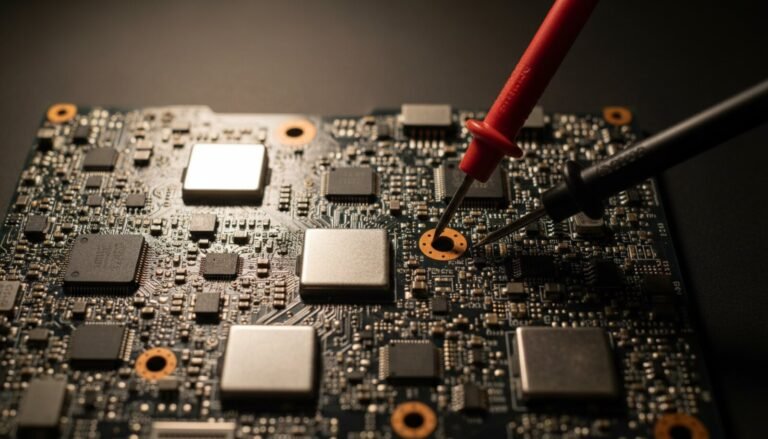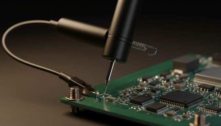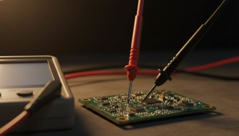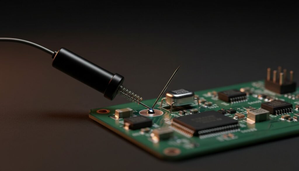
A multimeter answers how much. An oscilloscope answers when and what shape — and that is where the other half of board faults live. This is the bench-side companion to choosing your first oscilloscope: what to put the probe on, what the screen is actually telling you, and the two settings that quietly hide the fault you are hunting.
Four Knobs, Then Stop Turning Things
A scope has fifty controls. For board repair you use four:
- Volts/div. Volts per screen square. On a 3.3 V rail start at 1 V/div — the trace sits three squares up and stays on screen.
- Time/div. Time per square. Switching regulators live around 5 µs/div, MHz clocks around 100 ns/div, a whole power-on sequence around 100 ms/div. Aim for two or three cycles on screen: more is a blur, less is a lie.
- Trigger. The condition that tells the scope “start drawing here.” Rising edge, correct channel, level roughly halfway up the signal’s amplitude. A level above the peak never fires.
- Coupling. DC shows the whole signal including its resting level and is the default for almost everything. AC strips that level away so you can zoom in on what rides on top of it — the difference between “the rail is fine” and finding the fault.
The Flat Line That Isn’t a Measurement
The first trap is written into the instrument’s own design. Tektronix’s XYZs of Oscilloscopes primer describes the default trigger mode plainly: “Auto mode causes the oscilloscope to sweep, even without a trigger. If no signal is present, a timer in the oscilloscope triggers the sweep.”
Read that again with a dead board in front of you. In Auto mode a flat line means either the node really is flat, or the scope’s own timer is sweeping over a probe that slipped off the pad, a broken ground clip, or a channel you forgot to enable. The same primer notes that grounded input coupling plus auto trigger also produces “a horizontal line on the screen that represents zero volts.” Several different failures, one identical picture.
The fix takes ten seconds: touch the probe tip to the scope’s own calibration output, the square-wave post on the front panel. A clean square wave proves the probe, ground lead, channel and vertical settings are alive — and from that moment a flat line is real information. Then switch the trigger to Normal for hunting: it only sweeps when the condition is genuinely met, so a frozen screen is an honest answer instead of a comforting one.
The Part Nobody Covers: At 100 ms/div Your Scope Samples at 13 kSa/s
Every entry-level scope advertises a big sample rate. A current Tektronix TBS1000C, to take a public and typical spec sheet, lists 1 GS/s sample rate and — in much smaller print — 20 K points record length, on a graticule with 15 horizontal divisions. Those two numbers fight each other, and almost nobody does the arithmetic.
The record is a fixed bucket of 20,000 points covering whatever time span you asked for. At 1 GS/s those points last 20 µs, so the advertised rate only survives to roughly 1 µs/div. Slower time base, slower sampling — the primer states the rule and captions the consequence bluntly: “the slower the time base setting, the slower the sample rate”, beside a figure labelled “the glitch you will not see.”
| Time/div you set | Span on screen | Actual sample rate | Gap between points |
| 1 µs/div | 15 µs | ~1 GSa/s | ~1 ns |
| 1 ms/div | 15 ms | ~1.3 MSa/s | ~750 ns |
| 10 ms/div | 150 ms | ~133 kSa/s | ~7.5 µs |
| 100 ms/div | 1.5 s | ~13 kSa/s | ~75 µs |
Now put that against the most common single-shot job in repair: catching a power-on sequence. You set 100 ms/div, press Single, hit the power button — and in plain Sample mode the instrument takes one snapshot every 75 µs. An enable line that pulses high for 5 µs and gives up falls entirely between two samples. The screen shows a flat, well-behaved line and you spend the next hour blaming the wrong stage.
The cure is one menu away, and it is the most underused button on a repair bench: Peak Detect. Instead of one sample per interval, the scope stores the minimum and the maximum seen during it, and such scopes “run the ADC at a fast sample rate, even at very slow time base settings … and are able to capture fast signal changes that would occur between the waveform points if in sample mode.” The TBS1000C data sheet puts a number on it: peak detect “captures glitches as narrow as 4 nsec at all sweep speeds.” A 75-µs blind spot turned into a 4-ns one, for free.
Bench rule: turn Peak Detect on before you press Single, and leave it on for any time base slower than about 1 ms/div. Turn it off for ripple and noise, where it captures every spike faithfully and makes a clean rail look furry. There, use Hi-Res: it averages several samples into one point for “a decrease in noise and an improvement in resolution for low-speed signals”, and unlike averaging it “can be used even on a single shot event.”
Six Signals Worth Probing
In practice a scope chases the same short list, roughly in order of how often each is the culprit.
1. Ripple on the supply rails. AC coupling, 50 mV/div, probe at the output capacitor. A healthy rail is nearly a straight line with a few millivolts of fuzz; a 300 mV sawtooth is a dried-out filter capacitor — the classic fault a multimeter approves and the board rejects by locking up. Confirm the part with an ESR measurement.
2. The crystal. Probe the oscillator’s output pin, never in 1X, which loads it hard enough to stop it — see the probe-loading numbers. Either there is a dirty sine wave of a few MHz or there is not. A stopped crystal is the standard reason a board draws current and produces nothing.
3. Switching node and gate drive. On a buck converter’s MOSFET gate there should be a square wave of a few hundred kHz. Enable present but no switching means the controller is refusing, often because it sees a short downstream. Switching present but no output means the fault is after it: FET, inductor or load.
4. Enable and Power Good. The handshakes of the start-up chain, each rail authorising the next. In Single with Peak Detect on, you capture the cascade and see which step never happens — that is how “it doesn’t turn on” becomes “it stops at the third rail.”
5. I²C and SPI. Two lines sitting at 3.3 V read identically on a multimeter whether the bus is idle or dead. Only the waveform separates “the memory is blank” from “the memory is never even addressed” — the difference between reflashing a chip and chasing a broken trace.
6. Reset. It should go low briefly, then sit high and stable. Held low, it keeps the processor in a coma, and the culprit is usually the supervisor or its pull-up, not the processor everyone wants to replace.
Why Ripple Genuinely Needs AC Coupling
“Use AC coupling for ripple” gets repeated everywhere without the reason, and the reason is a hard number: vertical resolution. That data sheet lists 8 bits — 256 levels spread across the full height of the screen, roughly 25 steps per division. At 1 V/div one step is about 39 mV, so 30 mV of ripple on a 3.3 V rail is not “hard to see” in DC coupling; it is smaller than the smallest number the instrument can represent at that setting.
AC coupling removes the 3.3 V pedestal, letting you drop to 20 mV/div, where one step is under a millivolt. Same scope, same probe, roughly fifty times the resolution — you did not improve the instrument, you stopped spending its range on a DC level you already knew.
Two companions to that switch. The 20 MHz bandwidth limit button belongs on for ripple work, though the primer is honest that it “can also reduce or eliminate high-frequency signal content” — turn it off before looking at clocks or edges. And keep the ground lead short: a long pigtail invents ringing that is not on the board.
Reading the Screen
| What you see | What it means | Next move |
| Flat at zero | No signal — or a setup problem you have not ruled out | Verify on the cal output, then work back up the chain |
| Flat at a supply level | Voltage present, activity absent: that node is power, or an idle bus | Decide whether it should ever move; re-probe with Peak Detect during power-up |
| Clean square or sine | That stage is doing its job | Move downstream to the next stage |
| Rounded or drooping edges | Degraded signal — or an uncompensated probe | Compensate the probe first; only then suspect the board |
| Sawtooth on a DC level (AC coupled) | Ripple: filtering is compromised | ESR-test the output capacitors |
| Waves that appear and vanish in a cycle | Protection tripping and retrying — usually a short downstream | Current-limit the rail with a bench supply |
One rule ties it together: signal present at a stage’s input and absent at its output means the fault is inside that stage. The scope does not name the component — it corners the section. The multimeter and the schematic finish the job.
The Scope Is Not a Voltmeter
Before you trust a number off the screen: the TBS1000C specifies DC gain accuracy of ±3.0%. On a 3.3 V rail that is ±99 mV of legitimate error, against roughly ±1.5 mV for a decent handheld meter, as the multimeter spec sheets spell out. Scope for shape, timing and presence; meter for the value. Reaching for the scope to argue about 50 mV asks a question the instrument cannot answer.
Same discipline on safety: a bench scope’s probe ground is bonded to mains earth, so clipping it to the primary side of a live switching supply is a direct short — that measurement needs an isolation transformer or a differential probe.
Where This Sits in a Repair
The scope is the third instrument you reach for. A current-limited bench supply tells you whether the board is shorted; the multimeter tells you which rails are missing; component-level checks condemn individual parts. The scope enters when every voltage measures correct and the board still refuses. When the answer turns out to be firmware rather than hardware, the trail continues at the CH341A, the RT809H or the ESP32 flash tool, usually with a test clip on an 8-pin chip.
FAQ
My waveform keeps scrolling across the screen. What is wrong?
The trigger is not catching. Confirm the trigger source is the channel your probe is on, then set the level inside the signal’s amplitude, halfway up the waveform. A level above the peak or below the trough can never fire.
Can I measure ripple with a multimeter instead?
Partly. A true-RMS meter in AC tells you ripple exists and gives an approximate figure, but not the shape — and the shape separates a dried capacitor from a misbehaving switcher from injected noise. An alarm, not a verdict.
Why do I see noise that disappears when I move the probe?
Almost always the ground lead, not the board. A long ground pigtail forms a loop that picks up the switching fields around it. Use the shortest ground connection you have, landed near the point you are probing.
Do I need Peak Detect all the time?
No, and leaving it on will mislead you. It is the right mode for slow time bases and single-shot capture, where the real sample rate collapses. For ripple and noise it exaggerates every spike; use Hi-Res there.
Are cheap USB oscilloscopes good enough for this?
For ripple, switching waveforms and slow logic, yes — they show the shapes that matter and the software runs on the laptop already on your bench. The limits are modest bandwidth, a record length often shorter than a benchtop’s, and no isolation, so the mains-earth warning applies exactly the same.
The Verdict
The oscilloscope does not replace the multimeter; it starts where the multimeter stops. Three things carry the value. Four controls cover almost every measurement — volts/div, time/div, trigger and coupling. A flat line only means something after you have proven the setup on the calibration output, and Normal beats Auto for hunting. And the one that costs people whole afternoons: at the slow time bases a power-on sequence needs, your scope is sampling tens of thousands of times per second, not a billion, so Peak Detect goes on before you press Single.
Start with ripple on the rails in AC coupling: the easiest measurement on the instrument, and the one that most often exposes a board the multimeter already approved. Then capture the start-up sequence in Single, and you will watch, with your own eyes, precisely which step the board refuses to take.
Sources: Tektronix, XYZs of Oscilloscopes primer, and the Tektronix TBS1000C series data sheet. Verified August 2026.