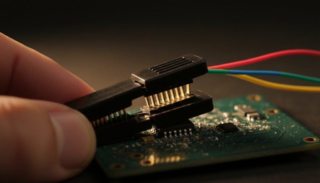
A SOIC-8 clip is the cheapest tool on the bench that decides whether a BIOS job takes four minutes or four hours. Get the fit, the pin 1 orientation and the voltage right and it just works; get any of the three wrong and you get a chip ID of 0x000000, a dump full of FF, or a dead chip.
This is the guide for the clip itself, not the programmer software. If you already own a clip, skip to voltage and the clip as a power supply.
What the Clip Actually Has to Match
People shop for a “SOIC-8 clip” as if SOIC-8 were one size. It isn’t. What is fixed is the pitch: 1.27 mm (0.050″) between lead centres. Winbond’s datasheets list e = 1.27 BSC for both the 150-mil and the 208-mil package, and Pomona prints “Chip Lead Spacing: 0.050″ (1,27)” right at the top of the 5250 datasheet. That is why one clip covers most 8-pin flash you will meet.
What changes is how wide the body is, and how far the legs splay out. That is the dimension your clip jaws have to swallow:
| Package | Body width | Lead-to-lead span | Clip fits? |
|---|---|---|---|
| SOIC-8 150-mil (narrow) | 3.90 mm nom. | 6.00 mm nom. | Yes |
| SOIC-8 208-mil (wide — most BIOS flash) | 5.28 mm nom. | 7.90 mm nom. | Yes |
| SOIC-16 / SOP-16 300-mil | ~7.5 mm | ~10.3 mm | Needs the 16-pin clip |
| WSON / USON / WLCSP | — | No leads at all | No |
Dimensions from the Winbond W25Q80DV and W25Q128JV datasheets (package specification sections).
Two things fall out of that table. First, a decent 8-pin clip handles both the narrow and the wide SOIC — the Pomona 5250 datasheet states it fits gull-wing and J-lead chips with body width from 0.150″ to 0.350″, which brackets everything above. Second, and this is where people waste an evening: the same flash die is sold in WSON, USON and WLCSP packages with no legs to clip onto — Winbond lists exactly those options for the W25Q80DV. If your chip is a flat pad-underneath part, no clip will grab it. That is a hot-air job (see the hot air rework station guide) and then a socket.
Find Pin 1 Before You Clip Anything
Every wasted hour I have watched on a flash job started with the clip on backwards. The chip tells you where pin 1 is with a dimple or a bevelled edge; the clip tells you nothing. Mark the pin-1 side of your clip with a dab of paint the day you buy it.
Standard SPI NOR flash pinout, straight from the Winbond W25Q128JV datasheet (8-pin SOIC, top view):
| Pin | Name | Pin | Name |
|---|---|---|---|
| 1 | /CS — chip select | 8 | VCC |
| 2 | DO (IO1) — data out | 7 | /HOLD or /RESET (IO3) |
| 3 | /WP (IO2) — write protect | 6 | CLK |
| 4 | GND | 5 | DI (IO0) — data in |
Note the diagonal: pin 4 is ground and pin 8 is VCC, on opposite corners. Reverse the clip and you put your programmer’s 3.3 V rail onto the chip’s ground pin and vice versa. Sometimes the chip survives that. Often it doesn’t.
Cheap ribbon cables mark pin 1 with a coloured stripe. Usually. Beep it out with a multimeter once, at the start, and never wonder again.
The $3 Clip vs. the Pomona
The flashrom project’s in-system programming documentation names Pomona and 3M as the clip vendors and puts distributor pricing at roughly US$20–50 — against about $3 for the generic clip that ships with every CH341A kit. Here is what the extra money actually buys, quoting the Pomona 5250 datasheet:
- Gold-plated lower contacts — the contact surface is the whole game. Tin-plated springs on the cheap clips oxidise, and an oxidised contact is an intermittent contact.
- Moulded barriers between each contact, which is what lets you clip onto a live board without shorting to the adjacent lead. On a cheap clip the jaws are bare metal fingers a fraction of a millimetre apart.
- 0.025″ square upper pins on 0.100″ spacing — standard header pitch, so any jumper wire or Dupont lead plugs straight in. No proprietary ribbon to lose.
The generic clip is not useless — it reads a chip on a bare board perfectly well. It fails in three predictable ways: the spring goes soft after a few dozen uses, the jaws catch only the tips of the gull-wing leads instead of the flat, and nothing stops them touching a neighbouring component.
Voltage: The Mistake That Actually Kills Chips
This is the one that turns a $3 mistake into a new motherboard.
Most SPI flash you meet is a 3.3 V part — the W25Q128JV runs at 2.7–3.6 V. But the identical-looking pinout-identical part number ending in W instead of V is a 1.8 V device. The W25Q128JW datasheet gives an operating range of 1.7–1.95 V and an absolute maximum VCC of 2.5 V, with the standard warning that “exposure beyond absolute maximum ratings may cause permanent damage.”
Clip a 3.3 V programmer onto a 1.8 V chip and you are 0.8 V past the absolute maximum on the supply pin, and further past it on every signal pin — the datasheet caps any pin at VCC + 0.4 V. The chip may read once and die, or die immediately. Read the part number off the chip before the clip touches it. The letter matters more than the capacity.
The same limit condemns a well-known shortcut. On a 3.3 V chip, VCC + 0.4 V is 3.7 V — so a programmer that drives 5 V logic onto CLK, DI and /CS is out of spec on every clock edge even when it appears to work. That is the whole reason the 5 V/3.3 V question keeps coming up around the black CH341A modules; it is covered in the CH341A + AsProgrammer guide.
In-Circuit or Off the Board?
Clipping a chip that is still soldered to a live board is the whole point of the clip, and where most failures live. The flashrom ISP documentation is blunt about the pitfalls:
- /WP and /HOLD must be tied to VCC. Leave pins 3 and 7 floating and you get, in flashrom’s words, strange issues — usually a chip that identifies but refuses to write. Good clips’ ribbons handle this; if you are wiring by hand, do it deliberately.
- The rest of the board fights you for the bus. The host chipset also drives CLK and /CS. Holding the board in reset is the standard answer — except that Intel ICH/PCH resets are edge-triggered, so holding reset simply does not work, and the ME inside those chipsets reads and writes the flash on its own.
- Power it from the board, not from the clip, when parts of the chipset light up parasitically through the flash’s VCC pin. flashrom recommends exactly that: disconnect VCC at the programmer and let the board’s own PSU bring the rail up.
- Contact goes unstable during erase and write. A read that fails is free. A write that fails halfway is a brick.
When in doubt on a laptop or a modern motherboard, desoldering the chip and reading it in a socket is not defeat — it is the faster path. A RT809H or an XGpro-driven T48/T56 in socket mode removes every variable in this section at once.
The Part Nobody Covers: Your Clip Is a Power Supply
Everyone treats the clip as a signal connection. During an erase it is a power connection, and a marginal one.
The W25Q128JV datasheet says it plainly: reading at 50 MHz draws 8 mA typical, 15 mA max, while Write Status Register, Page Program, Sector/Block Erase and Chip Erase each draw 20 mA typical, 25 mA max. The current roughly triples at precisely the moment the operation has become irreversible — and stays there for seconds, sometimes minutes on a chip erase, held up by nothing but eight spring fingers on eight oxidised legs.
There is a second detail in that table that catches people out. The erase and program currents are all specified with /CS = VCC — that is, measured with the chip deselected. The erase runs inside the chip after your programmer has finished talking to it. “The command went through, I can unclip now” is how boards get bricked. Watch the busy flag, not the log line.
- Support the board so nothing can nudge it. A clip that survives a read will drop contact if the cable is under tension for two minutes.
- Read the chip twice and compare the files before you write anything. Two identical dumps mean solid contact; two different dumps mean stop.
- Erase and write in one sitting, hands off the bench.
- If the chip ID changes between attempts, that is contact resistance, not a bad chip. Clean the legs with isopropyl and re-seat.
Reading a Bad Read
The symptoms map cleanly onto causes, and knowing the map stops you from replacing a perfectly good chip:
| What you see | What it usually is |
|---|---|
ID reads 0x000000 |
No power to the chip, or clip on backwards |
ID reads 0xFFFFFF |
DO not connected — pin 2 contact, or wrong clip orientation |
| ID changes between attempts | Contact resistance; oxidised legs or a tired spring |
Dump is all FF but ID is correct |
Bus contention — the host chipset is still driving the bus |
| Two dumps differ | Marginal contact. Do not write. |
| Identifies but will not write | /WP or /HOLD floating, or status-register protection set |
Where This Sits on the Bench
The clip is the front end of every SPI job on this site. It hangs off a CH341A for quick BIOS work, off an RT809F for TV boards, and off a flashrom setup if you are scripting it — with the caveat, covered in that guide, that flashrom on Windows cannot drive the internal programmer at all. If the read comes back clean and the board still won’t boot, the fault was never in the flash: go back to current-draw diagnostics and work the power rails.
FAQ
Does one SOIC-8 clip fit both 150-mil and 208-mil chips?
Yes. The pitch is 1.27 mm on both, and the Pomona 5250 is specified for body widths from 0.150″ to 0.350″. The wide 208-mil package is what you will find holding a PC BIOS.
Can I clip a WSON or USON flash chip?
No. Those packages have contact pads underneath the body and no protruding leads. Your options are an adapter board soldered to the pads, or removing the chip with hot air and reading it in a socket.
Do I have to power the board off before clipping?
For a read on a board you can fully de-energise, yes — it removes every bus-contention problem at once. On a board that must stay powered, the moulded barriers between contacts are exactly what the Pomona datasheet says they are for, and the cheap clips do not have them.
Why does my chip ID read correctly but the dump is all FF?
Almost always bus contention: the host chipset is still driving CLK or /CS. Hold the board in reset if it will hold — on Intel ICH/PCH the reset is edge-triggered and won’t — or pull the chip.
Is the expensive clip really worth it?
If you flash occasionally, no. If you flash for money, the first desolder-and-resolder it prevents costs more in your time than the clip did.
Verdict
Buy the cheap clip to learn on, and buy a proper one the week you start charging for the work. But the clip is the smaller half of the problem: read the part number for the V-or-W suffix before you apply power, mark pin 1 on the clip, and read twice before you ever write once. Those three habits prevent more dead boards than any amount of money spent on hardware.
And if reading that V-or-W suffix is the part you keep guessing at, the problem is not the clip — it is that the marking is a millimetre tall. A USB microscope fixes that for the price of a clip, and it needs no driver you do not already have.