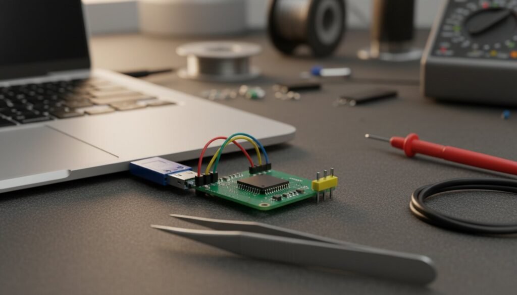
Every STM32 has a factory bootloader in system memory that can flash the chip over a plain USB-serial adapter, no ST-Link needed. When ST’s Flash Loader Demonstrator answers “No response from the target, the Boot loader can not be started”, the bootloader is almost never broken: it was not entered, it is listening on a different pin than the one you wired, or the PC is not sending the one byte it waits for (0x7F with even parity). Below: a hosted copy of stm32flash, the pin table ST publishes for each family, and the checks in order.
⬇ stm32flash 0.7 for Windows (open-source UART/I2C bootloader client)
Download stm32flash-0.7-binaries.zip
ST’s own tools (official, not mirrored): FLASHER-STM32 (STSW-MCU005), the Flash Loader Demonstrator, is marked NRND on ST’s page, “replaced by STM32CubeProgrammer”, and needs a myST login. STM32CubeProgrammer talks to the same UART bootloader (pick “UART” instead of “ST-LINK”). Install notes for it are in our ST-Link and CubeProgrammer guide.
What the bootloader expects on the wire
ST’s protocol note AN3155 (Rev 20, July 2025) is short on this point. After reset into system memory, the bootloader scans its USART RX pins for one frame: start bit, 0x7F, an even parity bit, stop bit. It measures that byte to pick the baud rate, answers 0x79 (ACK), and from then on rejects bad packets with 0x1F (NACK). ST tested 1200 to 115200 baud; the host must stay within 2.5% of the rate the chip derives. Two exceptions in the same note: the STM32WB0 series and the STM32WL3x line use no parity.
So a terminal program left at 8N1 never gets an answer, and neither does a chip whose RX pin you did not wire. stm32flash defaults to 8e1 at 57600 baud, which is why it often works where a hand-configured tool does not.
Which pins each STM32 listens on
The per-family pins below come from AN2606 (Rev 69, November 2025, 517 pages), section “Bootloader configuration” of each device. The last two columns come from stm32flash’s device table: the 0.7 release (57 product IDs) and the current SourceForge master (68 IDs, last commit 6 March 2026). If your chip is only in master, the hosted 0.7 binary stops with “Unknown/unsupported device”; use CubeProgrammer or build master.
| Device (typical board) | Entry pattern (AN2606 Table 2) | Bootloader USART pins (TX / RX) | stm32flash 0.7 | master |
|---|---|---|---|---|
| STM32F103 (Blue Pill) | BOOT0 = 1, BOOT1 (PB2) = 0 | USART1 PA9 / PA10 only | yes | yes |
| STM32F030x4/x6, F031 | BOOT0 = 1 and nBOOT1 bit = 1 | USART1 PA9 / PA10 or PA14 / PA15 | yes | yes |
| STM32F042, F070x6 | BOOT0 pin or nBOOT0 bit; also an empty chip | USART1 PA9 / PA10, USART2 PA14 / PA15 | yes | yes |
| STM32F072 (Discovery) | BOOT0 = 1 and nBOOT1 bit = 1 | USART1 PA9 / PA10, USART2 PA14 / PA15 | yes | yes |
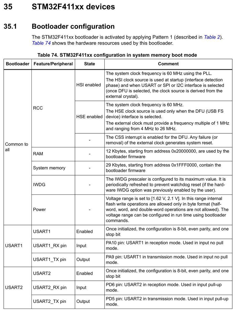
| STM32F401 / F411 (Black Pill) | BOOT0 = 1, BOOT1 = 0 | USART1 PA9 / PA10; USART2 on PD5 / PD6 | yes | yes |
| STM32F405 / F407 | BOOT0 = 1, BOOT1 = 0 | USART1 PA9 / PA10, USART3 PB10 / PB11 or PC10 / PC11 | yes | yes |
| STM32G030 / G031 / G041 | BOOT0 pin only if nBOOT_SEL = 0; else nBOOT0 bit or empty chip | USART1 PA9 / PA10, USART2 PA2 / PA3 | yes | yes |
| STM32G431 / G441 | BOOT0 pin if nSWBOOT0 = 1; else the nBOOT0 bit | USART1 PA9 / PA10, USART2 PA2 / PA3, USART3 PC10 / PC11 | yes | yes |
| STM32L031 / L041 | BOOT0 = 1 and nBOOT1 bit = 1 | USART2 on PA9 / PA10 or PA2 / PA3 | yes | yes |
| STM32L432 / L433 (Nucleo-32) | BOOT0 pin if nSWBOOT0 = 1; else nBOOT0 bit or empty chip | USART1 PA9 / PA10, USART2 PA2 / PA3, USART3 PC10 / PC11 | yes | yes |
| STM32H743 / H750 | BOOT = 1 with BOOT_ADD1 at system memory | USART1 PA9 / PA10 or PB14 / PB15, USART2 PA2 / PA3, USART3 PB10 / PB11 | yes | yes |
| STM32C011 | same rule as G0 (nBOOT_SEL) | USART1 PA9 / PA10 (on PA11 / PA12 in the SO8N, TSSOP20, UFQFN20 and WLCSP12 packages) | no | yes |
| STM32H723 / H733, H7A3, U575, WB55, WL55, L552 | see AN2606 per device | USART1 PA9 / PA10 on all of them | no | yes |
| STM32C031, C071, C092, H503, H563, U031, U073 | see AN2606 per device | USART1 PA9 / PA10 on most packages (check the AN2606 page) | no | no |
Two patterns in that table cause most of the forum threads. On the Black Pill, USART2 sits on PD5/PD6, which the board does not break out, so PA9/PA10 is the only UART way in. On the G0 and C0, the BOOT0 pin only counts when the option bit nBOOT_SEL is 0. An ST engineer wrote in 2020 that ST ships parts with nBOOT_SEL = 1 “by default ignoring BOOT0 pin”. A new chip still lands in the bootloader because its flash is empty, so the first upload works and every later one fails.
Flash it with stm32flash on Windows 11
- Install the adapter’s driver first if it is not a CDC device: CH340, CP2102, FTDI. Note the COM number in Device Manager.
- Set the adapter to 3.3 V. Wire adapter TX → STM32 RX (PA10), adapter RX → STM32 TX (PA9), and GND to GND.
- Set BOOT0 high (Blue Pill: BOOT0 jumper to 1, BOOT1 jumper to 0), then press reset. BOOT0 is only sampled at reset.
- Unzip and identify the chip:
stm32flash.exe COM5. A good answer prints the bootloader version andDevice ID : 0x0410 (STM32F10xxx Medium-density). - Flash and verify:
stm32flash.exe -w firmware.bin -v -g 0x0 COM5. For COM10 and above write\\.\COM10.
“No response from the target”: the causes in the order to check them
| What you see | Cause | Fix |
|---|---|---|
| Flash Loader: “No response from the target”; CubeProgrammer: “Activating device: KO”; stm32flash: “Failed to init device, timeout.” | Not in system memory: BOOT0 low, no reset after moving it, BOOT1 not 0, or (G0/C0) nBOOT_SEL = 1 | BOOT0 to 3.3 V, press reset. On G0/C0, clear nBOOT_SEL in the OB tab of CubeProgrammer over SWD |
| Same timeout, BOOT0 confirmed high | Wired to a USART the bootloader does not use, or TX/RX not crossed | Use the pins in the table above; adapter TX goes to the STM32 RX pin |
| Garbage or timeout with a terminal or custom script | 8N1 instead of 8E1 | Even parity, 8 data bits, 1 stop bit, 115200 or lower |
| Works on a bare chip, fails on a Nucleo | On-board ST-Link holds the BOOT0/SWCLK pin (C0 Nucleo) or the UART lines | Nucleo-C092: remove JP4, close SB14 (ST answer, Dec 2025) |
| stm32flash: “Got NACK from device on command 0x11” or “Failed to read memory at address 0x08000000, target write-protected?” | Bootloader is alive but read protection is on | -k sends Readout Unprotect: the bootloader erases the whole flash, clears RDP and resets (AN3155 §3.12). At RDP level 2 the bootloader does not start at all (AN2606 §4.1) |
| stm32flash: “Unknown/unsupported device (Device ID: 0x4xx)” | Chip newer than the 0.7 table | CubeProgrammer, or stm32flash built from master |
A second attempt without a reset can also fail. The bootloader has already locked the baud rate from the first 0x7F, so it reads the next 0x7F as the start of a command. stm32flash detects that and prints “Warning: the interface was not closed properly”; ST’s GUI tools just time out. Press reset between attempts.
If you have an ST-Link, SWD is the faster route and ignores BOOT0 entirely; see the ST-Link guide. For chips with USB DFU in the bootloader (F042, F072, F4, G4, L4, H7), the cable alone may be enough: STM32 DFU driver on Windows 11.
Sources
- STMicroelectronics, AN2606 Rev 69 (Table 2 activation patterns, Table 3 embedded bootloaders, per-device configuration tables)
- STMicroelectronics, AN3155 Rev 20 (0x7F, even parity, ACK 0x79 / NACK 0x1F, 1200–115200 baud, 2.5% tolerance)
- STMicroelectronics, FLASHER-STM32 product page (NRND, replaced by STM32CubeProgrammer)
- stm32flash: release files and MD5SUMS, dev_table.c (master),
stm32.candmain.cof release 0.7 (error strings, 8e1/57600 defaults) - Threads: ST Community, F107 “No response from the target”; ST Community, G030J6 and nBOOT_SEL; ST Community, programming a G030 over UART; ST Community, Nucleo-C092RC UART bootloading; ST Community, “Activating device: KO”; PlatformIO, Blue Pill “Failed to init device”