A 48 V pack that reads 0 V at the connector is almost never a pack with 0 V in it. It is a pack whose BMS has latched one of six protections — and reading five manufacturers’ datasheets side by side, the useful discovery is not the trip thresholds, which everybody quotes, but the release conditions, which nobody does. Each of the six lets you back in a different way, and that difference is a free diagnostic you can run with a multimeter, a charger and a screwdriver.
Every number below is per the datasheet, linked at the bottom, from what TI, Renesas, ABLIC and one BMS vendor publish for the chips that are actually on e-bike boards. They are typical defaults, not laws of nature: read the sheet for the chip on your board before you trust one.
The six protections, and what each one is watching
A lithium pack protector makes six decisions. Three watch a voltage across one cell, two watch a voltage across the shunt resistor, and one watches a thermistor. Everything else — state of charge, balancing, Bluetooth — is bookkeeping around those six.
| Protection | What it measures | What turns off | Typical delay | How it releases |
|---|---|---|---|---|
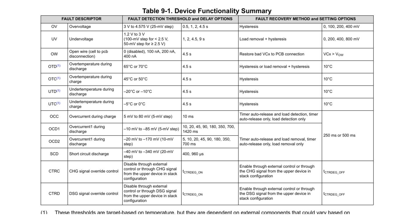
| OV — overcharge | Highest cell voltage | Charge FET | 0.5 s to 4.5 s | Hysteresis: the cell must fall below a lower release level |
| UV — overdischarge | Lowest cell voltage | Discharge FET | 1 s to 9 s | Load removal plus hysteresis — the release level is above the trip level |
| OCD — overcurrent, discharge | mV across the shunt | Discharge FET (often both) | 5 ms to 1.4 s | Load removal, a recovery timer, or load removal only |
| SCD — short circuit | mV across the shunt | Both FETs | 200 µs to 960 µs | Load removal (same state machine as OCD) |
| OCC — overcurrent, charge | mV across the shunt | Charge FET | 10 ms to 160 ms | Charger removal, detected by the chip itself |
| OT / UT — temperature | NTC thermistor | One or both FETs | 4.5 s | Hysteresis, typically 10 °C |
The cutoffs, by manufacturer
The cross-check, chip by chip. The ABLIC S-8254A is the cheap cascadable protector on hardware-only boards; the TI BQ77915 a standalone protector with factory-programmed thresholds; the Renesas ISL94203 a stand-alone monitor that lists e-bikes in its own applications list; the TI BQ76940 the analog front end under most “smart” 13S boards; and LLT Power a BMS manufacturer that publishes its default parameter table instead of hiding it.
| Protection | ABLIC S-8254A | TI BQ77915 | Renesas ISL94203 (defaults) | TI BQ76940 | LLT Power (published defaults) |
|---|---|---|---|---|---|
| OV trip / release | 3.90–4.45 V / 3.80–4.45 V, hysteresis 0–0.4 V | 3–4.575 V, hysteresis 0/100/200/400 mV | 4.25 V / 4.15 V; OVLO 4.35 V | 14-bit programmable | 4.25 ±0.03 V / 4.15 ±0.025 V (Li-ion) |
| UV trip / release | 2.0–3.0 V / 2.0–3.4 V, hysteresis 0–0.7 V | 1.2–3 V, hysteresis 0/200/400/800 mV | 2.7 V / 3.0 V; UVLO 1.8 V | 14-bit programmable | 2.7 ±0.1 V / 2.9 ±0.1 V |
| OCD threshold | 50–300 mV (level 1), 0.5 V (level 2) | −10 to −85 mV (OCD1), −20 to −170 mV (OCD2) | 4 to 96 mV (default 32 mV) | 8–100 mV | 150 mV |
| OCD delay | 10 ms typ. (level 1), 1 ms typ. (level 2) | 5 ms to 1420 ms | 160 ms | Programmable | 5 ms |
| SCD threshold / delay | VVC1 − 1.2 V / 300 µs typ. | −40 to −340 mV / 400 or 960 µs | 16–256 mV (default 128 mV) / 200 µs | 22–200 mV / from 400 µs | “external short with load” / 250 µs |
| OCC | None | 5–80 mV / 10 ms | 1–24 mV (default 8 mV) / 160 ms | Host decides | Not published |
| Temperature | None | OTD 65/70 °C · OTC 45/50 °C · UTD −20/−10 °C · UTC −5/0 °C, 10 °C hysteresis | Thresholds set in mV at the TEMPI pin | Host decides | Discharge 75 ±5 °C, release at 65 °C |
| Who clears the fault | The silicon | The silicon | The silicon (or a µC, optionally) | The host MCU only | Silicon + MCU, two layers |
Two rows are worth stopping on. The S-8254A — the protector on the cheapest hardware-only boards — has no temperature protection and no charge overcurrent protection at all. If a board built around it cuts out on a hot climb, the BMS did not do it on temperature, because that circuit does not exist. And the BQ76940, under a large share of “smart” boards, latches every fault until a microcontroller writes to it: “the host microcontroller must initiate all protection recovery”. There, a pack that stays dead may be a pack whose MCU is asleep, not one whose cells are flat.
The part nobody covers: the chip is actively asking whether the load is still there
Overcurrent and short-circuit recovery is usually described in forums as “it resets after a while”. On most of these chips it does not. It is a measurement, repeated until the answer changes.
The ISL94203 spells out the mechanism. After a discharge overcurrent or short circuit, it “waits three seconds and then periodically checks the load by turning on the LDMON output for 0 to 15 ms every 256 ms”, during which “the recovery circuit outputs a small current (~60 µA) to flow from the device and into the load”. If the load is still attached, that current finds a path, the pin stays low, and the fault stays set — cleared only after the load has been gone for two successive sample periods.
The S-8254A does the same job with a pull-up instead of a pulse: its overcurrent state clears only when the VMP pin rises above the level it calls VIOV3, which happens “because a charger is connected or the load (30 MΩ or more) is released”. The pull-up doing that work is 0.5–1.5 MΩ, so whatever stays connected across the terminals has to be enormous next to a megohm before the chip agrees the load is gone. The BQ77915 goes further: it has factory options where OCD1, OCD2 and SCD recovery is “load removal only”, with no timer anywhere in the path.
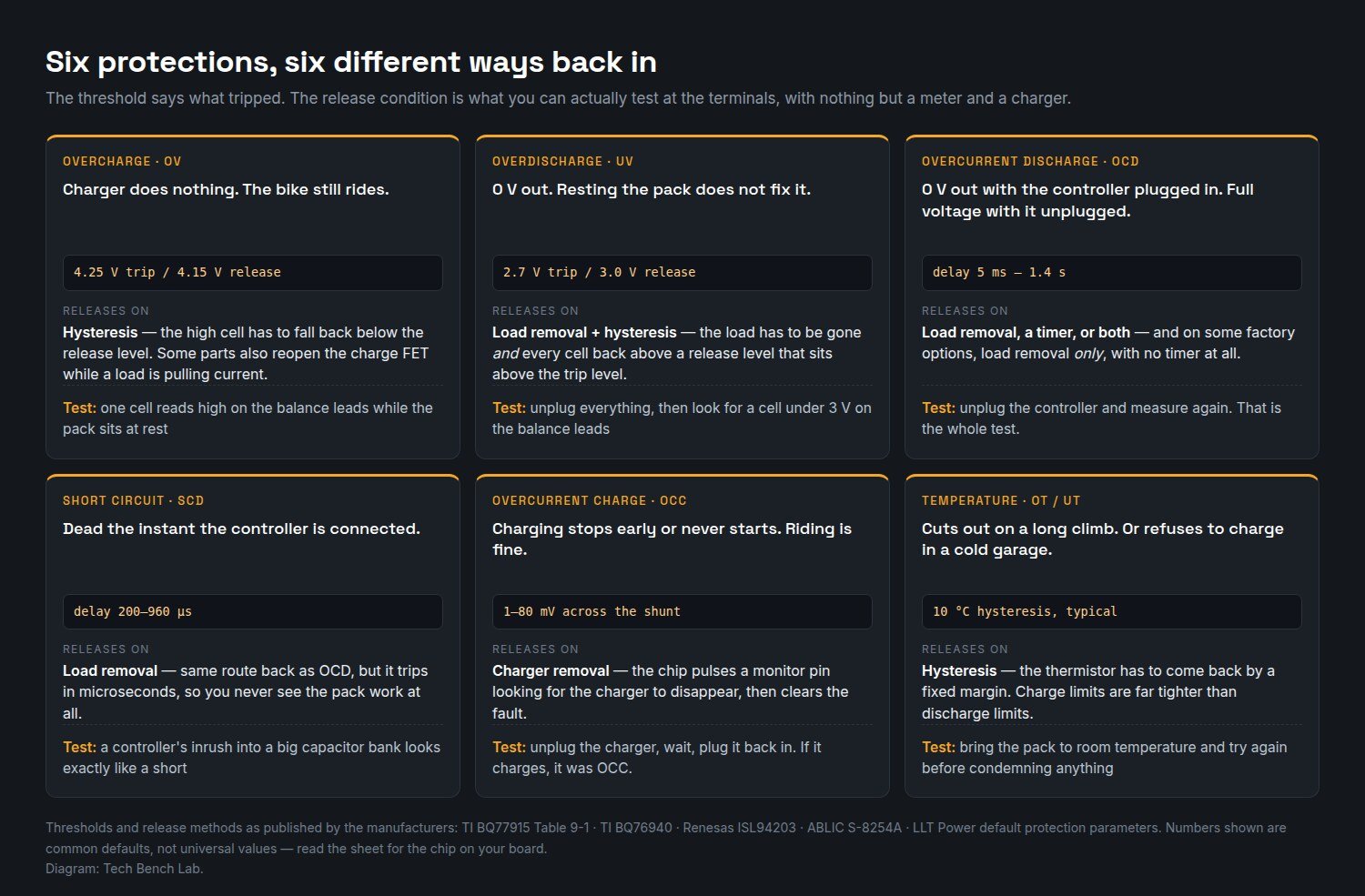
The practical consequence is the most misdiagnosed symptom in e-bike battery repair: the pack reads 0 V at the discharge connector with the controller plugged in, and full voltage with it unplugged. That is not an intermittent fault and not a bad connector. It is the published release condition, working as designed.
Running the diagnosis at the terminals
The order matters, because each step removes one family of causes.
- Measure B− to B+ on the pack side of the board, then P− to P+ on the output side, with nothing else connected. Full voltage on both means nothing is latched right now. Full voltage on B, zero on P means a protection is holding the discharge path off.
- Read every cell on the balance connector. One cell under the UV release level (2.9–3.0 V on typical defaults) explains a latched UV. One cell far above the others explains OV. Cells all sane and even means the fault is current or temperature, not voltage.
- Unplug the controller and measure the output again. If it comes back, you were looking at OCD or SCD and the board is fine — the question becomes what the controller was doing. A capacitor bank charging through a switch looks like a short for the first few hundred microseconds, which is inside the SCD window of every chip in the table above.
- Touch a charger to it. On several parts the charger is itself a release condition: the S-8254A drops its overdischarge hysteresis when a charger is present. A pack that wakes the moment a charger is connected was in UV, not in anything worse.
- Only then suspect the cells. Still 0 V out with no load, no charger and every cell above its release level? The fault is on the board — FETs, shunt path or the protector itself — which is ordinary board-level work.
Step 3 is the one people skip, because measuring “as installed” feels more thorough. It is the opposite: the meter is telling you the truth about a chip that is deliberately refusing to reconnect while it can still see a load.
The cutoffs that do not release
Lockout, not protection. The ISL94203’s undervoltage lockout default is 1.8 V per cell; below that the device powers down. The S-8254A’s overdischarge state pulls its own supply pin down and drops to 0.1 µA. The pack is then genuinely inert until something external forces the issue — and if the protector was ordered in the “0 V battery charge inhibited” option, even a charger will not restart it.
The fuse pin. The ISL94203’s PSD output goes active on overvoltage lockout and on open-wire faults, and the datasheet says it “can be used for blowing a fuse in the pack”. A blown fuse has no release condition. A pack that is dead in a way no unplugging fixes deserves that inspection before anything gets replaced.
The MCU that never woke up. On BQ76940-class boards every fault bit “remains latched high until cleared by the host”. A microcontroller that crashed, lost its supply rail or is waiting for a charger-detect that never comes will leave the front end holding the FETs off indefinitely, with healthy cells behind it.
Limits and common errors
A current threshold is a voltage threshold. Every chip in the table trips on millivolts across a shunt, not on amps. “100 A protection” is unauditable without the shunt value: 32 mV across 1 mΩ is 32 A, and across 0.5 mΩ it is 64 A. If you change the shunt, you have changed every current protection on the board.
A smart BMS has two layers that disagree. LLT Power’s published screenshots of the Xiaoxiang/JBD app show hardware overcurrent at 100 A / 8 ms and hardware short circuit at 200 A / 200 µs sitting underneath app-settable values, each with its own release timer (5 s after a short, 32 s after a discharge overcurrent). That is why the same pack sometimes returns after half a minute and sometimes only after everything is unplugged.
Delays this short are not multimeter territory. An SCD event lasts 200–960 µs; no handheld meter will show it, only the aftermath. Watching the event itself is a scope job.
Cold is a protection, not a fault. The BQ77915’s undertemperature-charge threshold is −5 °C or 0 °C. A pack that refuses to charge in an unheated garage and charges indoors is behaving exactly as specified.
Defaults are defaults. Every value in the second table can be changed by factory option, EEPROM or app. They are a starting point for the diagnosis, not a claim about your board.
Sources
- Texas Instruments — BQ77915 datasheet (SLUSCU0L), Table 9-1 fault recovery methods
- Texas Instruments — BQ76940 datasheet (host-initiated recovery, SYS_STAT latching)
- Renesas — ISL94203 datasheet FN7626 Rev 6.00 (LDMON/CHMON recovery, EEPROM defaults, PSD)
- ABLIC — S-8254A datasheet Rev 5.4 (release conditions, power-down, 0 V charge options)
- ABLIC — S-8209A datasheet Rev 3.8 (per-cell monitor with balancing)
- LLT Power — published default protection parameters for 12S–15S BMS boards
FAQ
My pack shows 0 V at the output but the cells are all at 3.9 V. Is the BMS dead?
Probably not. Unplug the load completely and measure again. Discharge overcurrent and short-circuit states release on load removal, and on some parts that is the only release path — so a pack in that state will keep reading 0 V for as long as the controller is attached, no matter how long you wait.
How long should I wait for a BMS to reset itself?
It depends on which protection tripped, and on some hardware the answer is “forever”. Timer-based recovery exists — 250 ms or 500 ms windows on the BQ77915, 5 s and 32 s release timers in the JBD app defaults — but load-removal-only options exist too, and a host-controlled front end waits for its MCU rather than a clock.
Why does my pack come back when I connect the charger?
Because on several protectors the charger is part of the release logic. The S-8254A drops its overdischarge hysteresis when a charger is connected, which lets the pack recover at the lower trip level instead of the higher release level. If a charger revives it, the fault was undervoltage.
Can I just bypass the BMS to test the pack?
You can, and for a five-second voltage check under a small load it tells you whether the cells hold up. What you give up is every one of the six protections at once, including the microsecond-scale short-circuit cutoff, on a pack that can deliver hundreds of amps. It is a measurement, not a repair, and it should end the moment the measurement does.
