Across 676 failure reports on the largest DIY solar forum, 40% never name a single component — the inverter “died”, “let out the smoke”, or “blew up”, and the thread ends in an RMA. Only 17% get as far as naming a semiconductor. This post does the part the threads skip: what actually fails on these boards, which five failures are bench-repairable, which three are not, and why the five-minute discharge wait printed in almost every manual is the time constant of one resistor rather than a property of the capacitor bank.
What 676 failure reports actually name
The population is defined so you can rebuild it. It is every thread in the DIY Solar Forum subforum “Magic Smoke Released… Learn From My Mistake!” (519 threads, 6 pages), plus 157 threads from the Inverters subforum (6,740 titles over 68 pages) whose titles carried a hardware-failure signature — smoke, burnt, fried, blew, dead, died, bricked, failed, no output, stopped working, repair, or a named part. That is 676 threads and 3.27 million characters of post text, read on 30 September 2026. Counts below are threads in which the term appears anywhere in the first page of posts.
| Component named | Threads | Share of 676 |
|---|---|---|
| Fuse | 188 | 27.8% |
| Cooling fan | 96 | 14.2% |
| Capacitor (electrolytic or bus) | 93 | 13.8% |
| Relay / contactor | 71 | 10.5% |
| Resistor (including precharge) | 69 | 10.2% |
| MOSFET | 63 | 9.3% |
| Transformer | 53 | 7.8% |
| Diode / rectifier | 49 | 7.2% |
| Shunt / current sensor | 48 | 7.1% |
| IGBT | 23 | 3.4% |
| MOV / surge suppressor | 22 | 3.3% |
| Optocoupler / isolator | 19 | 2.8% |
| Inductor / choke | 12 | 1.8% |
| Thermistor / NTC | 4 | 0.6% |
| Gate driver | 4 | 0.6% |
Read the shape rather than the ranking. The fuse leads because it is the one part a non-technical owner is expected to inspect. Below it sit the parts you can see with your eyes — fan, bulging capacitor, clicking relay, scorched resistor. The parts that need a schematic to discuss at all are at the bottom: 19 threads reach an optocoupler and four reach a gate driver, in a population selected for things that failed.
Three numbers carry the rest of the picture. 269 threads (40%) name no component whatsoever. 121 (18%) end in warranty, RMA, or a whole-unit swap. And 187 (28%) mention a loose connection, a torque problem, a crimp, a lug or corrosion — which is to say that in more than a quarter of “the inverter failed” reports, the suspect is the wiring rather than the board.
One caveat about the population: the Magic Smoke subforum collects failures of every kind, so its highest-traffic threads are battery fires, not inverter boards. The counts come from the text of all 676 threads and are not filtered to inverter-only faults — treat them as the vocabulary of solar hardware failure generally.
Eight manuals, one number, two philosophies
Every one of these boards sits behind a warning about stored charge. What the warnings differ on is whether they expect you to check. The table is the text of eight official manuals, downloaded on 30 September 2026.
| Inverter | Max DC input | Stated wait | Tells you to measure? |
|---|---|---|---|
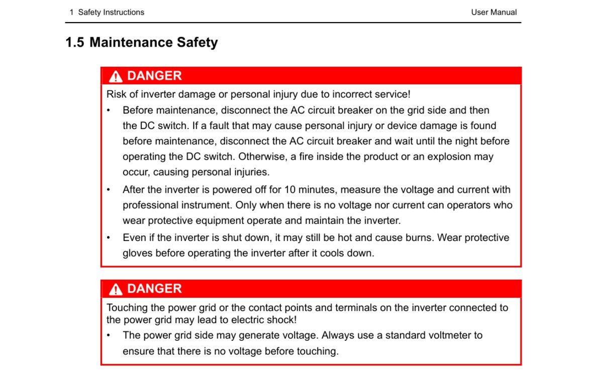
| Sungrow SH5.0–10RT | 1000 V | 10 min | Yes — “measure the voltage and current with professional instrument” |
| Schneider Conext CL 18/25 | 1000 V | 5 min | Yes — “always use a properly rated voltage sensing device” |
| MPP Solar HV V3 30 kW | 950 V | 5 min | No |
| Afore AF-SLP 7–12 kW | 550 V | 5 min | No |
| Deye SUN-3–6K-SG04LP1 | 500 V | 5 min (clock symbol) | No |
| EG4 8kEXP-240 | 500 V | 5 min (stated twice) | No |
| Megarevo R12–R16KLNA | 500 V | 5 min | No |
| Sol-Ark 15K-2P-LV | 500 VOC | none stated | No |
Six of the eight give you a stopwatch and no instrument. Sol-Ark’s 93-page installation manual, revision 11 dated 25 June 2026, is the outlier in the other direction: it warns repeatedly about shock and says the equipment “contains no user-serviceable parts”, but never mentions the internal capacitors and never gives a wait time at all. Sungrow is the one worth copying — ten minutes, then a measurement, and permission to proceed only “when there is no voltage nor current”.
The part nobody covers: the five minutes belong to a resistor
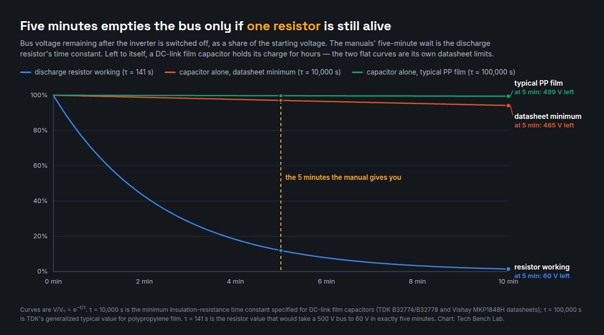
The wait exists because a DC-link capacitor bank holds charge. What the manuals do not say is that the capacitor is not what empties it. Film capacitor datasheets specify self-discharge as a time constant, τ = CR × Rins. TDK’s B32774/B32778 DC-link series specifies τ > 10,000 s after one minute for rated voltages at or above 500 V DC; Vishay’s MKP1848H DC-Link gives the same figure, “RC between leads, after 1 min > 10,000 s”. TDK’s general technical information for film capacitors puts the typical time constant for polypropylene — the dielectric these parts use — at 100,000 s.
Run those through V/V₀ = e−t/τ and the five minutes stops being a property of the capacitor.
| Discharge path | τ | 500 V bus after 5 min | Time to fall to 60 V |
|---|---|---|---|
| Bleeder resistor intact | 141 s | 60 V | 5 minutes |
| Capacitor alone, datasheet minimum | 10,000 s | 485 V | 5.9 hours |
| Capacitor alone, typical PP film | 100,000 s | 499 V | 59 hours |
A time constant of 141 seconds is precisely the resistor that takes a 500 V bus to 60 V in five minutes — which is where the number in the manuals comes from. Remove that resistor from the circuit and the same bus is still at 485 V after the wait, on the capacitor’s own worst-case specification. The instruction is off by a factor of about seventy.
This matters because an open resistor is not an exotic failure. It is one of the ordinary outcomes of the surge event that brought the board to your bench in the first place, and it is silent: nothing about a dead inverter tells you whether its discharge path survived. That is the whole argument for Sungrow’s wording. Measure the bus. Do not time it.
The five a bench tech can fix, and the three to leave alone
The split below is by repair economics and by what a replacement part does to the unit’s safety approval — not by difficulty. Plenty of the “do not touch” work is technically easy, which is exactly the trap.
| Verdict | Failure | Why |
|---|---|---|
| Fix | Cooling fans | Low-voltage, mechanical, keyed connector, no approval attached. A seized fan produces overtemperature derating and shutdown faults that read like power-stage failures. |
| Fix | Burnt terminals, lugs and connectors | The single most-cited fault class in the threads. Mechanical, inspectable, and a torque problem rather than a board problem. |
| Fix | Input fuses and the surge module | Designed to be sacrificial and replaceable. Replace like-for-like on voltage, interrupt rating and class — a DC fault needs a DC-rated part. |
| Fix | Precharge resistor and its relay | The classic killer: connecting a large battery straight to a large bus capacitor. Discrete, cheap, and its failure is visible as a scorched body or an open reading. |
| Fix | Auxiliary supply electrolytics, display and comms board | A dead display with a healthy bus is usually the low-voltage housekeeping supply, not the power stage. The comms daughterboard carries no mains at all. |
| Do not touch | The DC-link bank and its discharge path | Stored energy at up to 1000 V, and — per the arithmetic above — a wait time that is only true while one resistor is alive. |
| Do not touch | The switching bridge and its isolated gate drive | The isolation barrier is a certified property of the layout, not just of the part. See below. |
| Do not touch | Grid-protection relay and control firmware | Anti-islanding and grid disconnect are the certified functions the utility connection depends on. A substituted relay or patched firmware makes the unit non-compliant even if it runs. |
The gate-drive entry deserves its numbers, because “it’s just an isolator, I’ll fit an equivalent” is the most plausible-sounding mistake on the list. Take TI’s UCC21710, a reinforced isolated gate driver of the type used in this class of hardware. Its datasheet specifies external creepage and clearance greater than 8 mm, a maximum repetitive peak isolation voltage of 2121 VPK, transient and surge isolation of 8000 VPK, and apparent charge at or below 5 pC. It then adds the line that matters at a bench: the creepage and clearance of the board design must be maintained so that the mounting pads “do not reduce this distance”. The barrier is geometry. A flux bridge, a solder whisker, or a part in a smaller package with the same pinout defeats a certified 8 mm separation between a 500 V bus and everything a human can touch, and nothing in the unit’s behaviour will tell you that it happened.
How to work one of these safely
Kill the AC breaker first, then the DC switch, then the battery — the order Sungrow’s manual gives, because opening DC under load is what turns a fault into a fire. Wait the manual’s time. Then measure the bus directly with a meter you trust on a 500 to 1000 V DC circuit, which is a real constraint rather than a formality: a meter’s CAT rating and the fuse behind it decide what happens when you put probes on a live bus, and the two are frequently mismatched — the label and the fuse do not always agree. If the bus reads high after the wait, the discharge path is open; treat the board as live and discharge it deliberately through a resistor, never a screwdriver.
After that it is ordinary board repair. Inspect for the visible failures first. Read the electrolytics for ESR rather than capacitance, check the bridge devices in place before pulling them, and remember that a MOSFET failing a multimeter threshold test is often a good part measured at the wrong current. For the passives, the in-circuit rules hold: a reading can only be pulled low by parallel paths, so a high reading is always real.
Limits and common errors
The forum counts measure what people write, not what failed. A thread that says “the inverter is dead” may have had a shorted IGBT nobody looked for; the 40% figure is a statement about the written record, which is the point of the exercise, not a claim about physical failure rates. Keyword counting also has no idea whether a part was named as the culprit or as a suspect that was cleared — treat the table as vocabulary, not diagnosis.
Two errors are worth naming. The first is treating the manual’s wait as a measurement; it is a design assumption, and the arithmetic above shows how badly it fails when the assumption breaks. The second is assuming a battery-side inverter is low voltage because the battery is 48 V. Every unit in the table above accepts 500 V or more on its PV input, and that bus exists inside the case regardless of what the battery does — the same mistake people make with battery management boards, where the pack voltage tells you nothing about what the charger side is holding.
Sources
- DIY Solar Forum — “Magic Smoke Released… Learn From My Mistake!” (519 threads) and Inverters (6,740 thread titles), read 30 September 2026
- Sungrow SH5.0–10RT user manual (PDF), §1.5 Maintenance Safety
- Schneider Electric Conext CL 18/25 quick start guide (PDF)
- Sol-Ark 15K installation manual MA-00007 Rev 11 (PDF, 25 June 2026)
- EG4 8kEXP-240 user manual (PDF)
- Deye SUN-3–6K-SG04LP1-EU-SM2 user manual (PDF)
- Megarevo R12–R16KLNA hybrid inverter user manual (PDF)
- MPP Solar Hybrid V3 30 kW user manual (PDF) · Afore AF-SLP 7–12 kW user manual (PDF)
- TDK B32774/B32778 DC-link film capacitors · TDK, Film Capacitors — General technical information · Vishay MKP1848H DC-Link
- Texas Instruments UCC21710 reinforced isolated gate driver datasheet