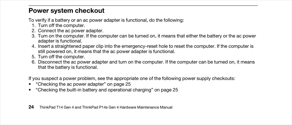
Lenovo publishes a Hardware Maintenance Manual for every ThinkPad T14, and the “no power” procedure in all four of them — Gen 1 through Gen 4 — contains exactly one number a meter can check: the coin cell, +2.5 to +3.2 V dc. Everything above that line is “turn it on and see,” and everything below it is “replace the system board.” Meanwhile Intel publishes, for the exact silicon in those same machines, 28 supply rails with DC specifications, 19 of them with a fixed voltage you can hold a probe to.
This post puts the two documents side by side and builds the tree Lenovo does not: where the power comes in, what it should read at each stage, and which readings look like faults but are not.
What the service manual actually contains
The four manuals are public downloads. We pulled them from Lenovo’s own server, extracted the text and counted.
| Manual | “Replace the system board” | Beep error codes | Measurable voltages in the whole book |
|---|---|---|---|
| T14 Gen 1 / P14s Gen 1 | 36 | 10 | 1 |
| T14 Gen 2 / P14s Gen 2 | 33 | 10 | 1 |
| T14 Gen 3 / P14s Gen 3 | 32 | 10 | 1 |
| T14 Gen 4 / P14s Gen 4 | 32 | 10 | 1 |
The ten beep codes — 0001 reset error, 0002 internal bus, 0281 general embedded controller, 0282 memory, 0283 PCI resource, 0284 and 0285 TCG, 0286 integrated graphics, 0287 discrete graphics, 0288 display — are identical across all four generations and six model years. Five of them (0002, 0281, 0284, 0285, 0286) list board replacement as the only action. The other five reach it as the last step. Ten out of ten end at the board.
That is not incompetence, it is scope: the manual is written for a depot that swaps assemblies under warranty. But if you are the person holding the board after the warranty, it hands you one usable instruction and one usable number:
- The observable: “If the system status indicator does not blink three times when an ac power source is connected, check the power cord of the ac power adapter.” Three blinks means the embedded controller saw the adapter.
- The number: coin cell red wire +2.5 to +3.2 V dc, black to ground. Immediately followed by: “If the voltage is correct, replace the system board.”
The power input: there is no barrel jack, and that changes the first measurement
Per Lenovo’s own PSREF specification sheets, every T14 from Gen 1 to Gen 4, Intel and AMD, charges only over USB-C Power Delivery. There are two USB-C ports on every model and both accept power. Gen 1 and Gen 2 add a third input — the side docking connector — which Gen 3 dropped.
| Model | USB-C ports accepting power | Side docking connector | Battery | Adapters offered |
|---|---|---|---|---|
| T14 Gen 1 (Intel / AMD) | 2 | Yes | 50 Wh | 45 W and 65 W USB-C, PD 3.0 |
| T14 Gen 2 (Intel / AMD) | 2 | Yes | 50 Wh | 45 W and 65 W USB-C, PD 3.0 |
| T14 Gen 3 (Intel / AMD) | 2 | No | 39.3 or 52.5 Wh | 45 W and 65 W USB-C, PD 3.0 |
| T14 Gen 4 (Intel / AMD) | 2 | No | 39.3 or 52.5 Wh | 45 W and 65 W USB-C, PD 3.0 |
Two consequences on the bench. First, swapping ports is a real A/B test between two front ends, exactly as it is on the Switch 2. Second, a USB-C source outputs nothing at all until it detects a sink — so “no voltage on the connector” is the expected reading from a healthy adapter into a board whose CC path is broken.
The numbers the USB specifications give you
These come from the current published specifications, not from a teardown: USB Power Delivery R3.2 V1.2 (August 2026) and USB Type-C R2.5 (March 2026), both downloadable from usb.org without a login.
| Stage | What you measure | Expected | Source |
|---|---|---|---|
| VBUS, off | VBUS to GND | vSafe0V: 0 to 0.8 V | PD R3.2, Table 4.8 |
| VBUS, attached but not negotiated | VBUS to GND | vSafe5V: 4.75 to 5.5 V | PD R3.2, Table 4.8 |
| VBUS, contract in place | VBUS to GND | PDO voltage × 0.95 to × 1.05 (20 V ⇒ 19.0–21.0 V) | PD R3.2, vSrcNew |
| Sink survivability | — | vSprMax 24 V: “a Sink Should tolerate this VBUS voltage without damage” | PD R3.2, Table 4.7 |
| CC termination | CC pin to GND, board unpowered | Rd = 5.1 kΩ ±20 %, on one CC pin only | Type-C R2.5 |
| CC, source advertising 3.0 A | CC pin to GND, attached | 1.369 to 2.042 V | Type-C R2.5, Table 4-36 |
| CC, source advertising 1.5 A | CC pin to GND, attached | 0.746 to 1.164 V | Type-C R2.5, Table 4-36 |
| CC, nothing detected | CC pin to GND | ≤ 0.276 V | Type-C R2.5, Table 4-36 |
CC is not brought out to a convenient pad on the mainboard; to read it you need a USB-C breakout or a PD analyser in line. But the numbers tell you what “working” looks like before you start suspecting the board.
The part nobody covers: a 45 W adapter is not allowed to offer 20 V
Lenovo shipped both a 45 W and a 65 W USB-C adapter with every T14 generation. Those two bricks do not offer the same voltages, and the difference is written into the Power Rules of the PD specification.
| Source Port Maximum PDP | 5 V | 9 V | 15 V | 20 V |
|---|---|---|---|---|
| 15 < x ≤ 27 W | 3 A | PDP ÷ 9 | — | — |
| 27 < x ≤ 45 W (the 45 W brick) | 3 A | 3 A | 3 A | not permitted |
| 45 < x ≤ 100 W (the 65 W brick) | 3 A | 3 A | 3 A | 3.25 A |
Table 3.1 sets the required fixed voltages by power rating, and §3.2.5.1 closes the door on going higher: a source “Shall Not Advertise an optional Fixed PDO voltage > the highest Required Fixed Voltage PDO in Table 3.1,” with optional fixed PDOs capped at 9 V anyway. So on a compliant 45 W adapter the ceiling is 15 V, and with tolerance the highest legal reading on VBUS is 15.75 V.
Read that the other way round and it saves a board: if you measure 15 V on a T14 that is charging slowly and conclude the PD negotiation failed to reach 20 V, you are diagnosing the adapter you grabbed off the shelf. Check the printed output table on the brick before you check anything on the board — adapters that predate the current Power Rules do exist, and the label is the final word on what that particular one offers.
The rails, generation by generation
Lenovo does not publish a schematic or a boardview for the T14, so nobody can give you a test point. Intel does publish, for the exact processors Lenovo lists in PSREF, the DC specification each rail must meet at the package. That tells you what a good rail looks like even when you have to find it yourself — the same exercise we did with a documented board in the MacBook Air M2 power sequence, and the reason reading a boardview matters so much when one exists.
| Generation | Processors (PSREF) | Intel datasheet | Fixed rails and typical values |
|---|---|---|---|
| Gen 1 Intel | i5-10210U/10310U, i7-10510U/10610U/10710U/10810U (Comet Lake U) | Doc 615211-008 | VccIO 0.95 V ±5 % · VDDQ 1.20 V ±5 % · VccST 1.05 V ±5 % · VccSTG 1.05 V ±5 % · VccPLL 1.05 V (1.0–1.1) |
| Gen 2 Intel | i5-1135G7/1145G7, i7-1165G7/1185G7 (Tiger Lake UP3) | Doc 631121 rev 012 | VccIN_AUX 1.8 V · VDD2 1.115 V (LPDDR4x) or 1.2 V (DDR4) ±5 % · VccST and VccSTG 1.025 V ±5 % |
| Gen 3 Intel | i5-1235U/1240P/1245U/1250P, i7-1255U/1260P/1265U/1270P/1280P (Alder Lake P/U) | Doc 655258-011 | Vcc1P05_PROC 1.05 V ±5 % · Vcc1P8_PROC 1.8 V ±4 % · VccIN_AUX 1.8 V · VCCANA 1.05 V · VCC_MIPILP 1.23 V · VDD2 1.065–1.2 V by DRAM type |
| Gen 4 Intel | i5-1335U/1340P/1345U/1350P, i7-1355U/1360P/1365U/1370P (Raptor Lake P/U) | Doc 743844-015 | Vcc1P05_PROC 1.05 V ±5 % · Vcc1P8_PROC 1.8 V ±4 % · VccIN_AUX 1.8 V · VDD2 1.065–1.2 V by DRAM type |
Two readings you should not misinterpret.
The core rail reading 0 V is correct on a dead board. Intel specifies VCCCORE as an “Operating Voltage Range” of 0 to 1.6 V, commanded by SVID — the regulator produces nothing until the processor asks. Same for graphics and, on Gen 1 and Gen 3, the system agent. If the board never starts, those rails are supposed to be at zero. Hunting a “missing” core voltage on a board that never powered up is hunting a symptom of the fault, never the fault.
The sustain rail changes address three times inside the same product line. On Gen 1, VccST and VccSTG are 1.05 V rails. On Gen 2 they are still specified at 1.025 V, but the datasheet says in a footnote that these rails “are not connect to external voltage regulator moreover they are connected to the VCC1P05 power rail (from PCH) through a power gate” — there is no inductor to probe, because there is no external regulator. On Gen 3 and Gen 4 an external rail comes back under a new name, Vcc1P05_PROC at 1.05 V, described as the rail that “support internal Sustain and Sustain Gated rails.” One more difference worth knowing: the 1.8 V PCIe PHY rail (Vcc1P8A) exists only on the H-series in the Tiger Lake generation, so it is absent from a Gen 2 T14 and present, as Vcc1P8_PROC, on Gen 3 and Gen 4.
Half of every T14 generation is AMD, and for those there is no equivalent. AMD’s published document for Renoir, Cezanne, Rembrandt and Phoenix is the Processor Programming Reference — a register map. There is no public AMD document that gives these mobile parts’ rail voltages the way Intel’s tables do.
The tree, in order
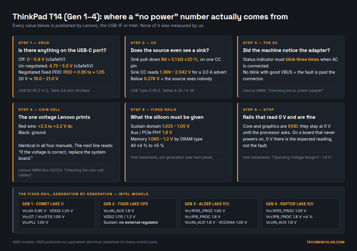
- Read the adapter label — 45 W or 65 W decides whether 20 V is even on the menu.
- VBUS on each of the two USB-C ports. 0–0.8 V with a good adapter on both ports points at the CC path or the adapter; 4.75–5.5 V that never rises means the contract never happened; a negotiated voltage within ±5 % means the input stage did its job.
- Status indicator on AC connect. Three blinks and the EC is alive and saw the adapter. Good VBUS and no blinks puts the fault past the connector.
- Coin cell, 2.5–3.2 V. The one number Lenovo prints. It will not stop the machine powering on, but it is free to check while the bottom cover is off.
- The fixed rails for that generation from the table above — sustain first, then the 1.8 V aux, then memory.
- Stop at the SVID rails. Zero there is the expected reading.
What the people who own these machines are actually asking
To size the problem we pulled every post from r/thinkpad and r/Lenovo between 1 May 2020 and 28 September 2026 through the Arctic Shift Reddit archive — 276,467 posts, of which 9,739 name the T14 in the title (T14s excluded). Filtering for titles that describe a machine that will not come up or will not take power, then rejecting by hand the ones that turned out to be about screens, docked peripherals or OS boot, and collapsing reposts and cross-posts, leaves 93 distinct incidents: 58 “will not turn on,” 35 “will not charge.”
| ThinkPad line | Titles in corpus | Power/no-boot titles | Share |
|---|---|---|---|
| T480 | 9,623 | 271 | 2.82 % |
| L14 | 1,795 | 35 | 1.95 % |
| T490 | 1,808 | 31 | 1.71 % |
| X1 Carbon | 7,179 | 122 | 1.70 % |
| P14s | 3,216 | 39 | 1.21 % |
| X13 | 2,490 | 29 | 1.16 % |
| T14 | 10,275 | 100 | 0.97 % |
Two things stand out. The T14 is the least power-complained-about line in the comparison, at roughly a third of the T480’s rate — this is not a machine with a famous power fault. And of the 93 incidents, 29 (31 %) received no reply at all, with a median of two comments on the rest. Among the posts that state a generation, Gen 2 leads with 23, then Gen 1 with 17 and Gen 3 with 11 — which tracks fleet age more than any design difference.
Limits
The Intel numbers are specified at the processor package, measured the way Intel describes: oscilloscope at 100 MHz bandwidth, probe ground lead under 5 mm. A multimeter on a rail capacitor is a coarser test, and it will not catch the AC component those tables also bound. No schematic or boardview is published for the T14, so nothing here tells you which inductor is which — it tells you what the reading has to be once you find it. And this covers Gen 1 through Gen 4 only; later generations ship under different manual bundles and different silicon, so the method carries over but the document numbers do not.
Sources
- Lenovo, Hardware Maintenance Manuals: T14 Gen 1 · Gen 2 · Gen 3 · Gen 4
- Lenovo PSREF specification sheets: T14 Gen 1 Intel · T14 Gen 4 AMD (same path pattern for every variant)
- USB Power Delivery Specification R3.2 V1.2, USB-IF, August 2026
- USB Type-C Cable and Connector Specification R2.5, USB-IF, March 2026
- Intel datasheets, volume 1: 10th Gen (615211-008) · 11th Gen Tiger Lake (631121) · 12th Gen (655258-011) · 13th Gen (743844-015)
- AMD Processor Programming Reference, Family 19h Model 70h — for contrast: registers, no electrical specifications
- Forum corpus: Arctic Shift archive of r/thinkpad and r/Lenovo, 1 May 2020 – 28 September 2026