NodeMCU PyFlasher is a single-file program for Windows and macOS that wraps esptool.py in a window with three choices: serial port, baud rate and flash mode. It writes one combined firmware image at address 0x00000, which is exactly what the NodeMCU cloud builder, Tasmota and MicroPython for ESP8266 hand you. Version 5.1.0 is hosted below with its checksum; the rest of this page is about the one radio button that decides whether the board boots afterwards.
⬇ NodeMCU PyFlasher 5.1.0 for Windows
Download NodeMCU PyFlasher 5.1.0 (Windows)
MIT licence, Copyright (c) 2016 Marcel Stör — full text. macOS: the official NodeMCU-PyFlasher.dmg (20 MB) is on the same release page; we do not mirror it. The .exe is not code-signed — the author’s words: “we don’t use code signing cert because…who’s gonna fund that for a free piece of software?” — so expect SmartScreen to object once. See the problems section.
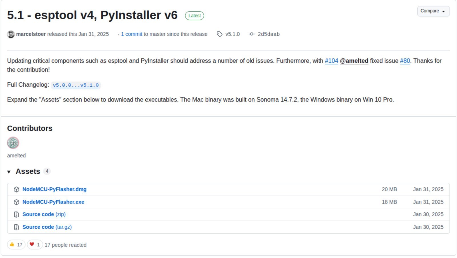
.dmg and the Windows .exe mirrored above. Screenshot: github.com/marcelstoer, 8 October 2026.What each version actually changed
The tool is a thin shell, so the version that matters is the esptool inside it. From the release notes and the repository’s requirements.txt:
| PyFlasher | Date | Bundled esptool | Notable |
| 5.1.0 | 31 Jan 2025 | 4.8.1 | PyInstaller 6.11, wxPython 4.2.2; rebuilt to “address a number of old issues”; flash-mode popup fix (#80) |
| 5.0.0 | 8 Apr 2021 | 3.0 | PyInstaller 4.2; the .exe silently failed to start on some Windows 10 machines (#78) |
| 4.0 | 17 Feb 2019 | 2.6 | Automatic port detection, MAC address printed, flashing a chip in deep sleep |
| 3.0 | 10 Feb 2018 | 2.2.1 | First macOS High Sierra binary; moved to Python 3 and wxPython 4 |
| 2.1 | 22 Oct 2017 | not stated (2.2 arrived with v2.2, Dec 2017) | DOUT mode added at Tasmota’s request (#20); no hard reset after flashing |
Using it on Windows 11
- Driver first. The board must already show as a COM port under Ports (COM & LPT). Most NodeMCU v3 and D1 mini clones use a CH340; the Amica NodeMCU v2 and many ESP32 DevKits use a CP2102;
- Unzip and double-click
NodeMCU-PyFlasher.exe. Being unsigned, it triggers SmartScreen’s “Windows protected your PC” the first time: More info → Run anyway; - Serial port: pick the COM port. “Auto-select” simply omits
--portand lets esptool scan; - NodeMCU firmware: Browse to the
.bin. One file only, always written at0x00000— this matters for ESP32, below; - Baud rate: start at 115200. Faster rates are fine when they work; if writing fails part way through, esptool’s own advice is to retry at a lower rate;
- Flash mode: use the table in the next section;
- Erase flash: “yes, wipes all data” the first time you put a different firmware on a board, or whenever it boot-loops. Tasmota’s documentation says the same: leave erase on for a first flash, turn it off only when upgrading and keeping settings;
- Click Flash NodeMCU. The console ends with esptool’s “Staying in bootloader.” and then the tool’s own line, “Firmware successfully flashed. Unplug/replug or reset device”. That is literal: the tool calls esptool with
--after no_reset, so the board does not reboot by itself.
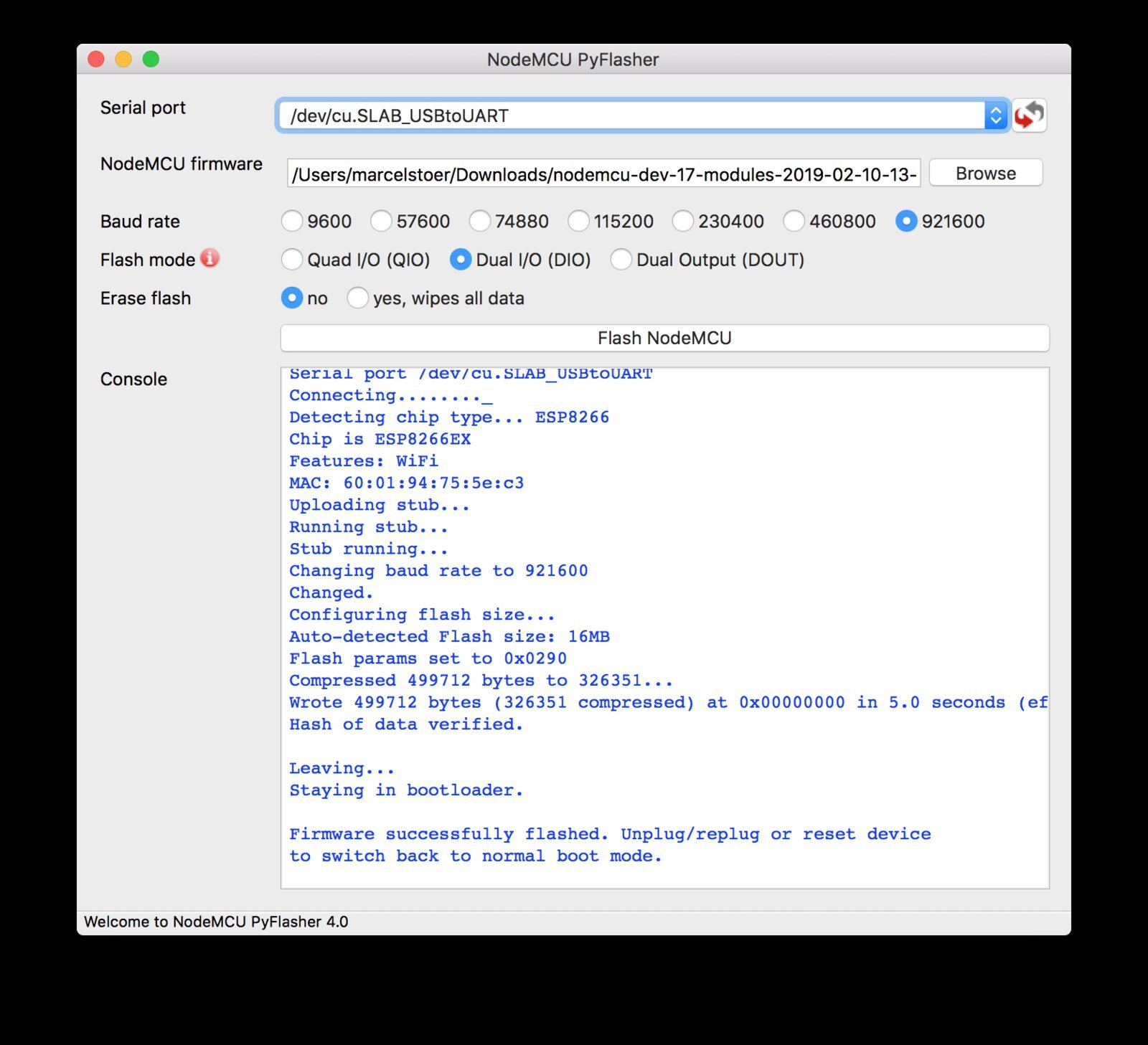
0x02 confirms DIO was written, 0x9 is 16 MB, 0x0 is 40 MHz. Image: Marcel Stör.Which flash mode for which board
The mode you pick is written into the image header, and the ROM uses that header for the first boot. Get it wrong and esptool’s troubleshooting page describes the result precisely: “Writing to flash with qio mode will succeed but the chip can’t read the flash back to run – so nothing happens on boot.” The tool’s own popup gives only three lines (most ESP32 and ESP-12 use DIO; most ESP-01/07 use QIO; ESP8285 requires DOUT). The table below is what each board’s maintainer declares in the boards.txt of the ESP8266 and ESP32 Arduino cores — the closest thing to a vendor statement of what the hardware supports.
| Board | Chip | Mode set by the core | Flash freq. | Image starts at |
| NodeMCU 1.0 (ESP-12E) — the usual “v2/v3” | ESP8266 | DIO | 40 MHz | 0x0 |
| NodeMCU 0.9 (ESP-12) | ESP8266 | QIO | 40 MHz | 0x0 |
| LOLIN/WEMOS D1 mini, D1 mini Pro, D1 R1/R2 | ESP8266 | DIO | 40 MHz | 0x0 |
| LOLIN D1 mini Lite | ESP8285 | DOUT | 40 MHz | 0x0 |
| Generic ESP8266 (ESP-01, ESP-01S, ESP-07, bare ESP-12F) | ESP8266 | Core default “DOUT (compatible)”; NodeMCU docs: QIO for most 512 KB ESP-01/07 | 40 MHz | 0x0 |
| Generic ESP8285, ITEAD Sonoff, DOIT ESP-Mx DevKit | ESP8285 | DOUT (the only mode that works) | 40 MHz | 0x0 |
| Adafruit Feather HUZZAH, SparkFun Thing, ESPino | ESP8266 | QIO | 40 MHz | 0x0 |
| ESP32 Dev Module, DOIT DevKit V1, NodeMCU-32S, LOLIN32, Wrover | ESP32 | DIO | 40 MHz | 0x1000 |
| ESP32-S2 Dev Module | ESP32-S2 | DIO | 80 MHz | 0x1000 |
| ESP32-S3 Dev Module | ESP32-S3 | DIO | 80 MHz | 0x0 |
| ESP32-C3 / C6 Dev Module | ESP32-C3 / C6 | QIO | 80 MHz | 0x0 |
What the table makes obvious: DOUT is the universal fallback. It is why Tasmota’s author asked for the mode in 2017 — manufacturers “have massively chosen for esp8285 which only supports DOUT”, and DOUT “works fine on both chips” — and why the Arduino core’s “Generic ESP8266” entry lists it first, marked “(compatible)”. The price, per esptool’s performance table, is about 50% slower cache refills than QIO, which shows on cache misses, not in running code.
The ESP32 catch: one file at 0x00000
PyFlasher has no address field. On the original ESP32 and the S2 the bootloader lives at 0x1000: MicroPython’s own download page says write_flash 0x1000 for ESP32_GENERIC, but write_flash 0 for the S3 and C3 boards. Feed an ESP32 image meant for 0x1000 to PyFlasher and the chip loops with flash read err, 1000 — the exact log in issue #29 (LOLIN32 Lite) and issue #60, where the answer was “you need to prepare the binary (i.e. combine the bootloader, apploader, app and partition binary files to one binary)”. So: use a merged image that starts at zero — Tasmota’s tasmota32.factory.bin is documented as write_flash 0x0, ESPEasy ships a PlatformIO post-script that produces firmware-factory.bin for the same purpose, and esptool’s merge_bin builds one from your own parts. For S3, C3 and C6 the normal image already starts at zero and the tool works as-is. Addresses and the rest of the manual route are in the esptool step-by-step guide; Espressif’s own GUI alternative is the Flash Download Tool.
The five things that go wrong, with the exact message
“Failed to connect to ESP8266: No serial data received.” (older esptool: “Timed out waiting for packet header”) — GPIO0 was not low at reset. A NodeMCU devkit does this through DTR/RTS; an ESP-01 or bare module needs GPIO0 held to GND while powering up, per the NodeMCU flashing docs. Esptool’s advice: check 3.3 V under load, try --baud 9600. In issue #58 an ESP8285 hung at this stage until the user swapped the USB-TTL adapter.
“Invalid head of packet (0x..): Possible serial noise or corruption.” — the chip is in normal boot, and its 74880-baud boot log is sitting in the receive buffer; esptool’s docs also list a bad cable, a breadboard shorting the SPI flash pins, and brown-out from an FTDI adapter’s 3.3 V pin.
“could not open port ‘COM8’: PermissionError(13, ‘Access is denied.'” — another program holds the port: an Arduino serial monitor, or a previous run. Reported against an ESP32-S3 in issue #99; the native USB-Serial/JTAG boards in that family also need to be put into download mode by hand (hold BOOT, tap RESET) before the tool can see them.
Flashed with “Hash of data verified”, then nothing — or fast blinking and rf_cal[0] !=0x05,is 0xFF. Two different faults. Silence is the wrong flash mode: switch to DOUT and flash again. The rf_cal message and endless reboots are stale SDK init data, which the NodeMCU docs say to cure by erasing the whole chip first — the “yes, wipes all data” radio button.
Nothing opens when you double-click, or the antivirus quarantines it. The silent-exit bug hit v5.0.0 on Windows 10 20H2 (issue #78, 32 comments, “v.4 x64 works”); the 5.1.0 rebuild with a current PyInstaller is the fix. The antivirus flag is a PyInstaller false positive: issue #107 reports the exact SHA-256 of the file mirrored above, and the author filed false-positive reports with eight vendors — “We’re now down to 10/71 on VirusTotal” two days later. Tasmota’s docs carry the same warning for their own PyInstaller build.
FAQ
Can I set the flash size? No. The command is hard-coded with --flash_size detect, and the author turned the request down in the DOUT thread: “I actually see value in providing as few knobs to turn as possible.”
Why is there no QOUT? Same thread: “I actually see no need for QOUT.” Nothing in the ESP8266 Arduino core defaults to it either.
Related
- esptool.py step by step — the command line underneath this GUI, with addresses
- ESP32 Flash Download Tool — Espressif’s GUI, multi-address
- CH340 driver for Windows and CP2102 driver — the two chips on almost every NodeMCU
- Arduino IDE 2 port not showing — when the COM port itself is missing
Sources
- marcelstoer/nodemcu-pyflasher — README, LICENSE,
Main.py(the esptool command it builds),requirements.txt, and the release notes - Issue #20 “Support Flash Mode Dout” — the Tasmota request and the author’s design position
- esptool: SPI Flash Modes, Troubleshooting, Firmware Image Format
- NodeMCU documentation: Flashing the firmware — flash mode by module, SDK init data, putting the device into flash mode
- ESP8266 Arduino core boards.txt and ESP32 Arduino core boards.txt —
build.flash_mode,build.flash_freq,build.bootloader_addrper board - Tasmota: Getting Started — erase-first rule, DOUT,
tasmota32.factory.binat 0x0, antivirus note - MicroPython ESP32_GENERIC and ESP32_GENERIC_S3 download pages — flash addresses