“Failed to connect to ESP8266: Timed out waiting for packet header” means esptool sent its sync packet and the chip never answered from its ROM bootloader. Usually the ESP8266 never entered download mode. Less often, the chip is in download mode and the reply gets lost between the board and the PC. The fastest way to tell which is the 74880-baud boot line the chip prints on every reset. Below: how to read that line bit by bit, which boards reset themselves into download mode and which don’t, and a Linux kernel bug that produced this exact error on CH340 boards in 2021.
⬇ Before you start: driver and port
CH340 driver for Windows 11 (hosted, with SHA-256)
CP2102 / CP210x driver (hosted, with SHA-256)
No COM port at all? That’s a driver or cable problem: see Arduino IDE 2 port not showing. For the fix below you don’t need to download anything. The tools are esptool (bundled with the Arduino ESP8266 core, or installed on its own) and any serial terminal that can do 74880 baud.
Why ESP8266 users still see this wording
esptool stopped printing “Timed out waiting for packet header” in v3.2 (October 2021). Newer versions print “No serial data received” for the same failure. The Arduino ESP8266 core’s latest release, 3.1.2, still pins esptool to the v3.0 commit from November 2020, so every Arduino ESP8266 upload uses the old wording (details and counts in our esptool guide). Same failure, same fixes.
Step 1: read the boot line at 74880 baud
Open the board’s port at 74880 baud and press RST. According to the esptool docs, the boot ROM prints its log at that unusual rate, and pySerial’s python -m serial.tools.miniterm COM5 74880 supports it on every OS. You’ll get a line like ets Jan 8 2013,rst cause:2, boot mode:(3,6). The Arduino ESP8266 core documentation gives the formula for the first number: (GPIO15 << 2) | (GPIO0 << 1) | GPIO2, which is the level of the three strapping pins at reset:
| boot mode:(N,x) | GPIO15 / GPIO0 / GPIO2 | Mode | What it tells you |
|---|---|---|---|
| 1 | 0 / 0 / 1 | UART download | The chip is in download mode. The problem is the port, the baud rate, the driver or the host (step 4). |
| 3 | 0 / 1 / 1 | Boot from flash | Normal run. If you see this while holding FLASH, GPIO0 isn’t reaching 0 V: bad button, or something on D3/GPIO0 holding it high. |
| 0, 2 | 0 / x / 0 | Not valid | GPIO2 (D4) is low at reset. Look for an LED, relay or sensor on D4 pulling it down. |
| 4, 5, 6, 7 | 1 / x / x | SDIO | GPIO15 (D8) is high at reset. Disconnect whatever is on D8. The board needs its pull-down there. |
For the reset cause, the esptool docs list 1 = power-on, 2 = external reset (RST pin), 4 = hardware watchdog. Two real cases: in esptool issue #653 the user’s NodeMCU printed boot mode:(1,7) after FLASH+RST, so the board was fine and the fault was on the PC side. In Arduino forum thread 1376334, a CP2102 Amica board kept printing (5,x) and (7,x), which is GPIO15 high. No change of port, board type or driver can fix that.
If nothing at all appears at 74880 when you press RST, the problem is before the chip: swap the cable first (charge-only cables are common), then suspect the USB bridge. In thread 1159116, a second board turned out to be missing the USB chip’s resonator and its two capacitors.
Step 2: does your board reset itself into download mode?
esptool pulls GPIO0 low and pulses EN/RST using the adapter’s DTR and RTS lines. Dev boards do this with two cross-coupled transistors, so opening the port (DTR and RTS both asserted) doesn’t hold the chip in reset. The NodeMCU schematic prints the truth table: DTR/RTS 1/1 and 0/0 → RST 1, GPIO0 1; 1/0 → RST 0 (reset); 0/1 → GPIO0 0 (download).
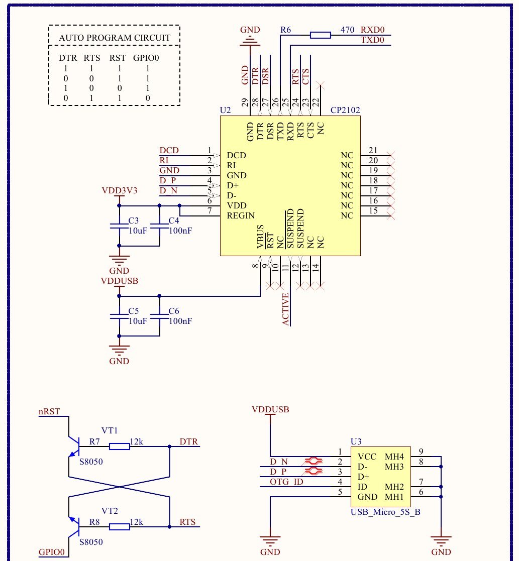
| Board | USB chip | Auto-reset | Capacitor on reset line | Source |
|---|---|---|---|---|
| NodeMCU DEVKIT V1.0 (official) | CP2102 | Yes, 2× S8050, 12 kΩ | 100 nF on nRST; EN has a 12 kΩ pull-up only | Schematic sheets 2 and 3 |
| LOLIN D1 mini V3.0.0 | CH340C | Yes, UMH3N dual transistor | 100 nF (C9) on RST | WEMOS schematic |
| LOLIN D1 mini V4.0.0 (USB-C) | CH340C | Yes, UMH3N | 100 nF (C14) on RST | WEMOS schematic |
| Adafruit Feather HUZZAH ESP8266 | CP2104 | Yes | not published in the core docs | Arduino ESP8266 core board list |
| “NodeMCU V3” (LoLin clone) | usually CH340G | Varies | no official schematic | Check the board itself |
| ESP-01 / ESP-01S, bare ESP-12F | none | No | n/a | Arduino ESP8266 core “minimal hardware setup” |
The esptool docs warn that some third-party boards use the reset circuit without a capacitor on EN, which “results in unreliable automatic reset, especially on Windows”. They suggest adding 1 µF or more from EN to GND. For any board, the manual fallback is the same: hold FLASH, tap RST, release FLASH, then start the upload.
Step 3: bare modules (ESP-01, ESP-12F on a USB-TTL adapter)
Here nothing happens automatically. The Arduino ESP8266 core documents the minimum setup for flashing: adapter TX → RX and RX → TX, GPIO0 to GND, GPIO15 pull-down, CH_PD (EN) pull-up, and RST on the adapter’s RTS. If you don’t use RTS, you have to power-cycle the module by hand. The same page notes that tying a pin straight to VCC or GND “is not a substitute” for a pull-up/pull-down resistor. The adapter must be 3.3 V. Per the esptool troubleshooting page, the ESP needs up to 70 mA continuous and 200–300 mA peaks, and the 3.3 V output of FT232R adapters “do[es] not supply sufficient current”. Power the module from a separate 3.3 V regulator.
Step 4: chip in download mode, still no reply
If the boot line says (1,x) and it still fails, work through the host side. Use the right COM port, and close any Serial Monitor or terminal holding it (esptool docs: “a common pitfall”). Drop Upload Speed to 115200; the docs suggest -b 9600 as a test. On Linux, also check the kernel. In the stable kernels of August 2021, the ch341 driver gained a 512-byte receive buffer (“fix character loss at high transfer rates”). The CH340 doesn’t send a zero-length packet when a reply exactly fills its endpoint, so esptool’s replies stalled. That’s kernel bug 214131, and the revert commit df7b16d1c00e explains it. CP2102 boards and ESP32 boards were not affected. From the kernel.org stable changelogs:
| Kernel series | Broken from | Fixed in |
|---|---|---|
| 5.4 LTS | 5.4.140 | 5.4.144 |
| 5.10 LTS | 5.10.58 | 5.10.62 |
| 5.13 | 5.13.10 | 5.13.14 |
| 5.14 | release candidates (reported up to rc5) | 5.14 final |
| Ubuntu 20.04 (distro kernels, user reports in #653) | 5.4.0-88, 5.11.0-37 | 5.4.0-86 and 5.11.0-36 worked |
Check with uname -r. If you’re in a broken range, update the kernel or boot the previous one. Updating esptool won’t help, because the bug is in the kernel. For brltty grabbing the port on Ubuntu, see CH340 on macOS and Linux.
The checks, in order
- Close every program on the port and confirm the COM number (unplug and replug, then see which entry disappears).
- Read the 74880 boot line while holding FLASH and tapping RST.
(3,x): GPIO0 isn’t going low. Use the manual FLASH/RST sequence, check the button, or add 1–10 µF from EN to GND.(0/2/4–7,x): disconnect whatever is on D4 (GPIO2) or D8 (GPIO15).(1,x): lower the baud rate, check the cable and driver, and on Linux check the kernel table above.- Nothing printed at all: try another cable and another USB port, then suspect the USB bridge.
Related: NodeMCU PyFlasher (flash modes per board), ESP32 “Wrong boot mode detected (0x13)” (the ESP32 equivalent of this page), esptool step by step.
Sources
- esptool docs (ESP8266): Boot Mode Selection (required pins, auto-reset, EN capacitor, boot log, rst cause), Troubleshooting (power, 74880 baud, CH340 kernel note)
- Arduino ESP8266 core: Boards (boot mode formula, minimal hardware setup, board list)
- Schematics: NodeMCU DEVKIT V1.0, LOLIN D1 mini (V3.0.0 and V4.0.0 PDFs)
- Linux: bug 214131, stable changelogs 5.13.10 / 5.13.14, 5.10.58 / 5.10.62, 5.4.140 / 5.4.144
- Threads: esptool #653, Arduino forum 1159116, 1376334, 1110412, PlatformIO 25863 (Ubuntu 5.13.0-28 + CH340)